1
2
3
4
5
6
1
2
3
4
5
6
1
2
3
4
5
6
1
2
3
4
5
6
F
GB
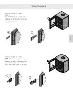
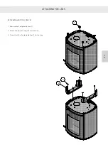
Lift the stove up onto the wall bracket and push it into place against
the wall until it ‘clicks’ into place (3).
Check that the top plate of the stove is horizontally level. If it is not,
it may necessary to lift the stove down from the wall and adjust the
bracket.
M4 thread for pointed screws
Mount the bottommost wall bracket (4) under the stove using
two M6 screws.
Use the centremost M6 screw (6) to adjust the stove so it is plumb.
Attach the bracket to the wall, if preferred, but do not tighten the
screws due the stove’s downward movement during heating.
Finally, screw two M4 pointed screws (6) into each side of the wall
bracket which locks the stove in relation to the bracket.
See the photo at the top of the page.
Summary of Contents for Attika Q-Tee C 57 Classic
Page 2: ...DK DK DK DK...
Page 43: ...1 2 3 4 5 9 6 7 8 10 DK 42 RESERVEDELSTEGNING DK DK DK DK...
Page 45: ...2 9 6 7 8 10 1 3 4 5 DK 44 RESERVEDELSTEGNING DK DK DK DK...
Page 47: ...2 9 6 7 8 10 1 3 4 5 DK 46 RESERVEDELSTEGNING DK DK DK DK...
Page 49: ...10 1 7 8 2 3 4 9 6 5 DK 48 RESERVEDELSTEGNING DK DK DK DK...
Page 50: ...49 DK DK DK DK DK...
Page 53: ...DK 52 YDEEVNEDEKLARATION DK DK DK DK...
Page 54: ...D...
Page 95: ...1 2 3 4 5 9 6 7 8 10 D ERSATZTEILZEICHNUNG...
Page 97: ...2 9 6 7 8 10 1 3 4 5 D ERSATZTEILZEICHNUNG...
Page 99: ...2 9 6 7 8 10 1 3 4 5 D ERSATZTEILZEICHNUNG...
Page 101: ...10 1 7 8 2 3 4 9 6 5 D ERSATZTEILZEICHNUNG...
Page 102: ...D...
Page 103: ...D PR FUNGSBESCHEINIGUNG...
Page 105: ...D LEISTUNGSERKL RUNG...
Page 106: ...GB...
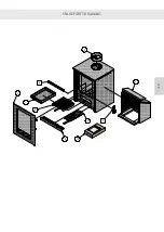
Page 147: ...1 2 3 4 5 9 6 7 8 10 GB SPARE PARTS DRAWING...
Page 149: ...2 9 6 7 8 10 1 3 4 5 GB SPARE PARTS DRAWING...
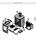
Page 151: ...2 9 6 7 8 10 1 3 4 5 GB SPARE PARTS DRAWING...
Page 153: ...10 1 7 8 2 3 4 9 6 5 GB SPARE PARTS DRAWING...
Page 154: ...GB...
Page 157: ...GB DECLARATION OF PERFORMANCE...
Page 198: ...1 2 3 4 5 9 6 7 8 10 F DESSIN DE PI CE DE RECHANGE...
Page 200: ...2 9 6 7 8 10 1 3 4 5 F DESSIN DE PI CE DE RECHANGE...
Page 202: ...2 9 6 7 8 10 1 3 4 5 F DESSIN DE PI CE DE RECHANGE...
Page 204: ...10 1 7 8 2 3 4 9 6 5 F DESSIN DE PI CE DE RECHANGE...
Page 205: ...F...
Page 208: ...F D CLARATION DES PERFORMANCES...
Page 209: ...NO...
Page 230: ...800 NO AVSTANDER Avstand til brennbart uisolert r ykr r Brennbart tak...
Page 232: ...800 NO AVSTANDER Avstand til brennbart uisolert r ykr r Brennbart tak...
Page 250: ...1 2 3 4 5 9 6 7 8 10 NO RESERVEDELSTEGNING...
Page 252: ...2 9 6 7 8 10 1 3 4 5 NO RESERVEDELSTEGNING...
Page 254: ...2 9 6 7 8 10 1 3 4 5 NO RESERVEDELSTEGNING...
Page 256: ...10 1 7 8 2 3 4 9 6 5 NO RESERVEDELSTEGNING...
Page 257: ...NO...
Page 260: ...NO YTELSESERKL RING...
Page 261: ...S...
Page 302: ...1 2 3 4 5 9 6 7 8 10 S RESERVDELSRITNING...
Page 304: ...2 9 6 7 8 10 1 3 4 5 S RESERVDELSRITNING...
Page 306: ...2 9 6 7 8 10 1 3 4 5 S RESERVDELSRITNING...
Page 308: ...10 1 7 8 2 3 4 9 6 5 S RESERVDELSRITNING...
Page 309: ...S...
Page 312: ...S PRESTANDADEKLARATION...
Page 313: ......
Page 354: ...1 2 3 4 5 9 6 7 8 10 SF VARAOSAPIIRUSTUS...
Page 356: ...2 9 6 7 8 10 1 3 4 5 SF VARAOSAPIIRUSTUS...
Page 358: ...2 9 6 7 8 10 1 3 4 5 SF VARAOSAPIIRUSTUS...
Page 360: ...10 1 7 8 2 3 4 9 6 5 SF VARAOSAPIIRUSTUS...
Page 361: ...SF...
Page 364: ...SF SUORITUSTASOILMOITUS...


