USER MANUAL --Raiscube A8R 3D Printer
17
STEP FOUR
What remaining is circuit connection, including end-stops. There are several wire terminals to
connect to its matching terminal one by one. Please refer to the marks to make it easier.
Please note that it is required to install X Axis end-stop at this step two. Please locate “X
end-stop support” on left of upper rod, where its switch get triggered when Nozzle just reaches
left margin of hotbed.
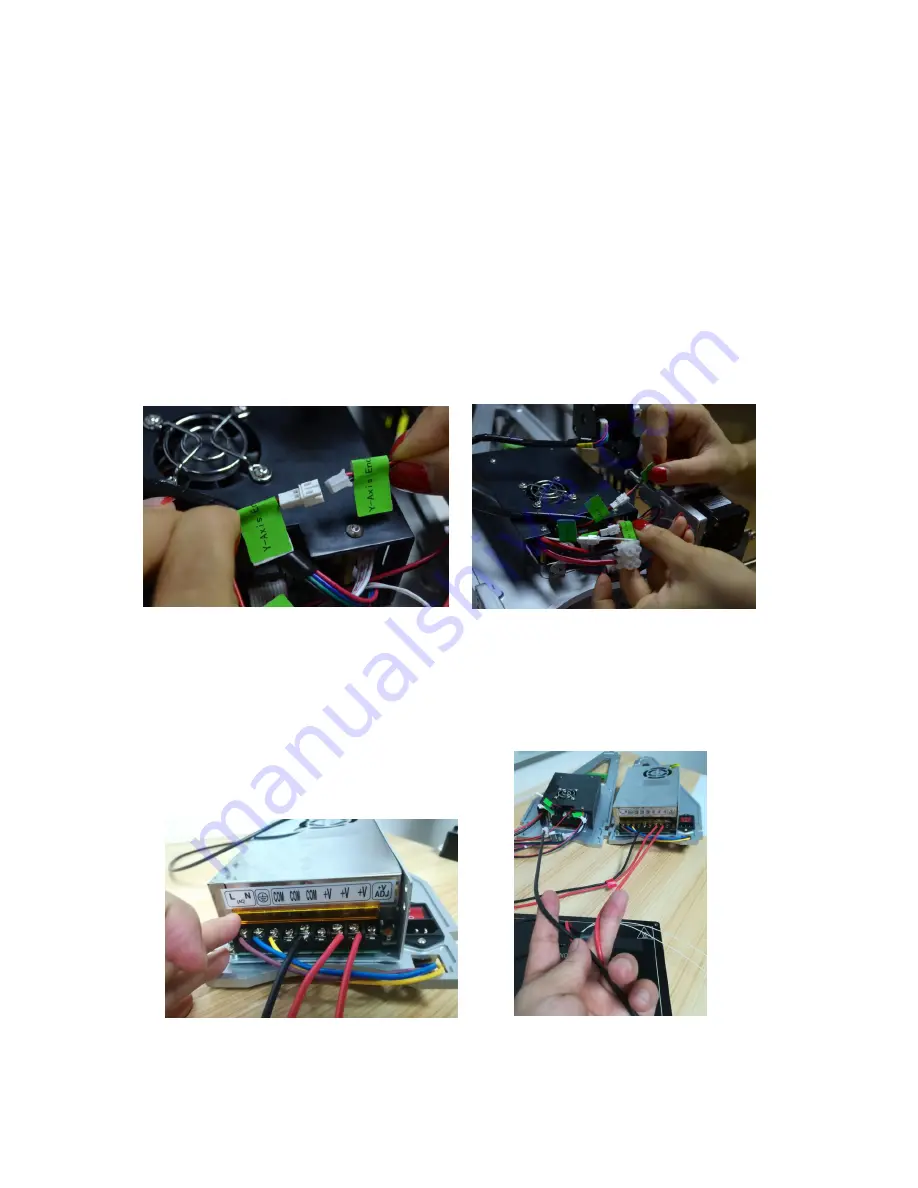
A8R wire is pre-assembled, thus to connect circuit, need to read marks on each cord, and
match one with the other of same mark. For example, “Y Axis End-stop” with “Y Axis En-stop”
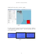
as in Fig.w01. And Fig.w02 shows joints of connection between motherboard and other
function modules in circuit.
Fig.w01
Fig.w02
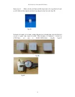
Please also note that when connecting motherboard to power supply, there are one red, and
one black cord piece. Red for “V+”, Black for “COM”. (Fig.w03). Please note that there is one
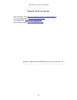
more Red cord connecting to the PSU “V+” from Heat bed.
In fact, Heat bed Red cord (“+”) go
to PSU “V+”, while Black Cord (“-”) connect with the terminal from Main Board.(Fig.w03-h)
Fig.w03
Fig.w03-h


