


Pro2-Series
3D Printer
/ Quick Start Guide
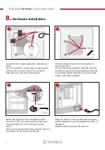
B.
Hardware Installation
(continued)
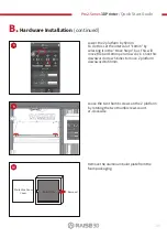
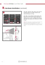
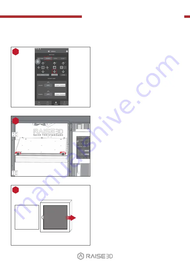
Lower the Z platform by 50mm.
To do this, set the interval at "10mm" by
selecting it in the "Move Steps" bar. This will
move the bed 10mm per arrow click. Click this
downward arrow 5 times to move Z platform
downward to 50mm.
8
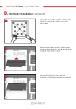
Remove the aluminum build plate from the
foam packaging.
10
Protective Foam
Cover
Build Plate
Remove!
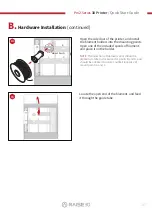
Loose the two thumb screws on the Z platform
by rotating the two thumbscrews count-
er-clockwise.
9
01
02
03
04
05
06
07
08
09
10
11
12
13
14
15
16
17
18
19
20
21
22
23
26
24
25
27


