


Pro3 Series
3D Printer
/ User Manual
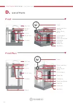
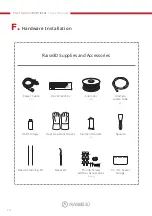
F.
Hardware Installation
10
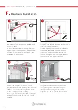
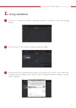
Adjust the flatness of the build plate.
Precise flatness helps to get a better
bottom surface of the model, avoiding
warping or the model detaching from
the build surface.
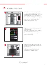
11
Adjust the matching gap between the
left and right nozzles to ensure that the
model will not be staggered in dual-col-
or printing.
12
It aims to verify whether the adjust-
ments in the previous four wizards are
appropriate.
18