Raisecom Technology Co., Ltd.
http://www.raisecom.com
- 11 -
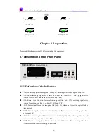
3.1.3 Fiber Optic Interface
For the dual-strand models, the fiber optic interface is DSC/PC. TX stands for optical signal
output (transmit); RX stands for optical signal input (receive).
3.2 Dip-switch SW1 Setup on the Bottom Panel
The dip-switch SW1 on the bottom panel must be set up before use.
1
st
~ 5
th
bit: V.35 interface bandwidth setup
6
th
bit: bandwidth master control/slave control setup
7
th
~ 8
th
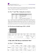
bit: timing resource option
3.2.1 The 1
st
~ 5
th
Bit: V.35 Interface Bandwidth Setup
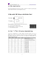
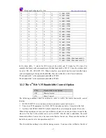
V.35 bit rate is N*64kbps (N=1~31) when working at fractional E1 mode; V.35 bit rate is
2048kbps when working at transparent E1 mode. These 5 bits of the dip-switch are actually
representing the binary code of the N value. When N is configured to 0, RC801-30B-FV35 is
working at transparent E1 mode.
1
st
bit
2
nd
bit
3
rd
bit
4
th
bit
5
th
bit
Bandwidth (bit/s)
0 0 0 0 0 2048K
(transparent
E1
mode)
0 0 0 0 1 1×64K=64K
(minimum
bandwidth)
0 0 0 1 0 2×64K=128K
0 0 0 1 1 3×64K=192K
0 0 1 0 0 4×64K=256K
0 0 1 0 1 5×64K=320K
0 0 1 1 0 6×64K=384K
0 0 1 1 1 7×64K=448K
0 1 0 0 0 8×64K=512K
0 1 0 0 1 9×64K=576K
0 1 0 1 0 10×64K=640K
0 1 0 1 1 11×64K=704K
0 1 1 0 0 12×64K=768K
1 2 3 4 5 6 7 8
ON
OF


