background image

  Raisecom Technology Co., Ltd.                                                         

http://www.raisecom.com


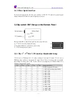
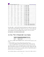
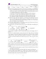
- 13 - 

the Master Clock site, or at the Slave Clock site. 


If any of the three conditions cannot be met, then both modems shall be set to Master Control and 

the first 5 bits will be used to configure the actual bandwidth. Please note that when N=0, the 

equipment is working at transparent mode and this bit switch is invalid. 

3.2.3 The 7

th

 and 8

th

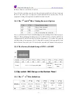
 Bits: Timing Resource Option 

7

th

 bit 

8

th

 bit 

Timing Resource Option 

OFF OFF Master 

Clock (Internal) 

OFF ON  V.35 

Terminal 

Clock 

ON OFF Vacant 

ON 

ON 

Slave Clock (follow the link clock) 

Users are advised to select the most suitable timing resource according to the connection types in 

Chapter 2. When configuring the timing resource, V.35 DTE interface on Routers shall also be 

configured. Both TX and RX clock shall be External Clock mode at V.35 interface that connected 

with Master/Slave Clock equipment. The TX Clock shall be Internal Clock mode and RX Clock 

shall be External Clock mode at the V.35 interface that connected with Terminal Clock equipment. 

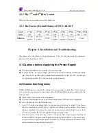
3.2.4


The Factory Default Setup of SW1: All OFF 


Switch 1

st

 bit 

2

nd

 bit 

3

rd

 bit 

4

th

 bit 

5

th

 bit 

6

th

 bit 

7

th

 bit 

8

th

 bit 

Default OFF OFF OFF OFF OFF  OFF  OFF OFF 

Details N=31

V.35 bandwidth 1984K 

Bandwidth 

Master 

Control 

Master Clock 

Mode 

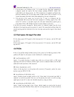
3.3 Dip-switch SW2 Setup on the Bottom Panel 

3.3.1 The 1

st

 ~ 6

th

 Bits Definition 

1

st

 bit 

2

nd

 bit 

3

rd

 bit 

4

th

 bit 

5

th

 bit 

6

th

 bit 

Definition 

TX CLK 

phase 

RX CLK 

phase 

PCM30/31

Option 

CRC 

function 

option 

Loop-back 

test 

Loop-back 

option 

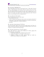
ON 

Negative Negative  PCM30  Disable Loop-back 

Local 

Summary of Contents for RC802-30B-FV35 series

Page 1: ...Raisecom Technology Co Ltd http www raisecom com 1 RC802 30B FV35 Series N 64K V 35 Interface Fiber Optic Modem User Manual Raisecom Technology Co Ltd...

Page 2: ...2 2 1 Point to point Fractional Mode Master Clock Slave Clock Topology 7 2 2 2 Point to point Fractional Mode Terminal Clock Slave Clock Topology 7 2 2 3 Point to point Transparent Mode Master Clock M...

Page 3: ...echnology Co Ltd http www raisecom com 3 CHAPTER 4 INSTALLATION AND TROUBLESHOOTING 15 4 1 CAUTIONS BEFORE APPLYING THE POWER SUPPLY 15 4 2 CONNECTION DIAGNOSIS 15 4 3 FAULT PASS THROUGH FUNCTION 16 4...

Page 4: ...the local site to realize the remote management 1 1 Main Features 1 2 Product Specifications 1 2 1 Fiber Optic Interface Specification Bit rate 100Mbps Line code 4B5B Fiber connecter SC Optical Transm...

Page 5: ...d No 16 timeslot shall be skipped if N is larger than 16 TS 1 TS 31 V 35 BANWIDTH TS N 1 TS 0 TS 16 1 2 4 Power Supply Power Supply DC 48V tolerance range from 36V to 72V AC 220V tolerance range from...

Page 6: ...m the fiber optic receiving link also called Restoring Clock Terminal Clock Mode The timing resource is provided by the DTE also called System Clock 2 1 2 Compatibility If RC801 30B FV35 is connected...

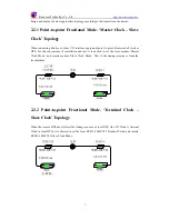
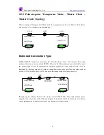
Page 7: ...shall work as DTE For the convenience of installation and test it is advised to set the local modem Master Clock Mode and remote modem Slave Clock Mode That is the timing resource is from the local m...

Page 8: ...modem which will convert the optical signals to G 703 compliant E1 electrical signals and then connect with a V 35 to fractional E1 interface converter Users can adopt Raisecom series interface conve...

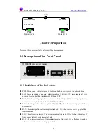
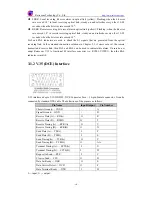
Page 9: ...l link red ON receiving signal error occurs at local optical link include AIS LOF and CRC RAL Remote receiving signal error alarm in optical link red ON receiving signal error occurs at remote optical...

Page 10: ...r at the remote transmit and receive link then LAL and RAL can be used to indicate this alarm If users do not adopt Raisecom V 35 to fractional E1 interface converter i e RC903 V35FE1 then the RAL ind...

Page 11: ...erface Bandwidth Setup V 35 bit rate is N 64kbps N 1 31 when working at fractional E1 mode V 35 bit rate is 2048kbps when working at transparent E1 mode These 5 bits of the dip switch are actually rep...

Page 12: ...the above table for switch status Max bandwidth 1 is the maximum bandwidth in PCM30 Max bandwidth 2 is the maximum bandwidth in PCM31 3 2 2 The 6th Bit V 35 Bandwidth Control Option 6th bit Bandwidth...

Page 13: ...en configuring the timing resource V 35 DTE interface on Routers shall also be configured Both TX and RX clock shall be External Clock mode at V 35 interface that connected with Master Slave Clock equ...

Page 14: ...e link requirement The local and remote sites shall have the same configuration Loop back test is the auxiliary function used for users to test and diagnose the equipment and link Local Loop back is p...

Page 15: ...t not be reversely connected 4 2 Connection Diagnosis LERR or RERR indicator may be ON when just after connecting the optical fiber This is because a few error bits are generated by connecting cables...

Page 16: ...LAL alarm appears DCD signals will be disconnected at V 35 interface and the DTE shall response that If RAL alarm appears CTS signals will be disconnected at V 35 interface and the DTE shall response...

Page 17: ...resource setup 2 Check V 35 interface status of the Router if there are data errors on input and output then it indicates that TX CLKand RX CLK phase relationship need to be adjusted This problem can...

Page 18: ...raisecom com 18 BROADBAND To RAISECOM Copyright Declaration Raisecom Technology Co Ltd is the owner of this manual booklet The part or whole of this manual is not allowed to reproduce without Raiseco...

Reviews: