background image

www.raisecom.com                                                                                                                                     

 User Manual


28           

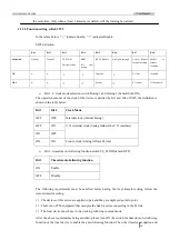
                                            Please check whether the E1 cable has been connected properly, and whether the TX and RX 

of the BNC cable are correctly connected. 


Summary of Contents for RC831-60-FV35 Series

Page 1: ...www raisecom com RC831 60 FV35 User Manual ...

Page 2: ...age without the prior written consent of Raisecom Technology Co Ltd The information contained in this document is subject to change without notice Copyright Notices Copyright 2007 Raisecom All rights reserved No part of this publication may be excerpted reproduced translated or utilized in any form or by any means electronic or mechanical including photocopying and microfilm without permission in ...

Page 3: ... 10 82883056 World Wide Web You can access the most current Raisecom product information on the World Wide Web at the following URL http www raisecom com Feedback Comments and questions about how the RC831 60 FV35 A device works are welcomed Please review the FAQ in the related manual and if your question is not covered send email by using the following web page http www raisecom com en xcontactus...

Page 4: ...12 4 1 3 Default settings 18 Chapter 5 Basic Connection and Typical Application 19 5 1 Basic connection 19 5 1 1 Connect the optical interface 19 5 1 2 Connect the E1 interface 20 5 1 3 Connect to the power supply 20 5 2 Typical application 20 5 2 1 Point to point internal clock line in clock structure 20 5 2 2 Point to point V 35 terminal clock line in clock structure 21 Chapter 6 Network Managem...

Page 5: ...Release Notes Date of Release Manual Version Revisions 20071114 200706 REV A ...

Page 6: ...ble is intact and is connected to the transmitter Do not attempt to adjust the laser drive current Do not use broken or unterminated fiber optic cables connectors or look straight at the laser beam The use of optical devices with the equipment will increase eye hazard Use of controls adjustments or performing procedures other than those specified herein may result in hazardous radiation exposure A...

Page 7: ...estricted access area i e an area where access is authorized only to qualified service and maintenance personnel Make sure that the DC supply is electrically isolated from any AC source and that the installation complies with the local codes Before connecting the DC supply wires ensure that power is removed from the DC circuit Locate the circuit breaker of the panel board that services the equipme...

Page 8: ... supports both framed E1 and unframed transparent E1 transmission mode For V 35 interface working at framed mode the bandwidth of the V 35 interface can be configured to N x 64Kbps N 1 31 by setting a succession of bits of the corresponding DIP switch and the bandwidth can also be configured by assigning time slots in the network management system The V 35 interface provides 3 clock modes internal...

Page 9: ...oth 75Ω unbalanced E1 interface BNC and 120Ω balanced E1 interface RJ 45 1 optical interface single strand two wavelength optical interface Tx wavelength 1310nm transmission distance 0 25km single power supply 220V AC power supply RC831 60 FV35 SS15 AC Stand alone device 1 line of V 35 signal 1 line of E1 signal including both 75Ω unbalanced E1 interface BNC and 120Ω balanced E1 interface RJ 45 1 ...

Page 10: ...Ω balanced E1 interface RJ 45 1 optical interface dual strand single mode transmission distance 15 120km single power supply 48V DC power supply RC831 60 FV35 SS13 DC Stand alone device 1 line of V 35 signal 1 line of E1 signal including both 75Ω unbalanced E1 interface BNC and 120Ω balanced E1 interface RJ 45 1 optical interface single strand two wavelength optical interface Tx wavelength 1310nm ...

Page 11: ...ith same optical transceivers can inter connect with each other For example RC831 60 FV35 S1 can be inter connected with RC831 30 FV35 S1 RC831 240 BL S1 and other RC831 series devices with S1 optical transceivers Among RC831 series devices adopting optical transceivers for single strand fiber device with SS13 can communicate with device with SS15 while device with SS23 can communicate with device...

Page 12: ...smission parameter different optical transceivers have different optical interface parameters please see the table below Optical transceiver Wavelength nm Transmitting Optical Power dBm Overload dBm Extinction Ratio dB Receiving Sensibility dBm Transmission Distance Km M 1310 20 14 14 8 2 28 0 2 S1 1310 15 8 8 8 2 34 0 25 S2 1310 5 0 8 8 2 34 10 60 S3 1550 5 0 10 10 36 15 120 SS13 1310 12 3 8 8 2 ...

Page 13: ... Allowance 18 36V Power consumption 10W 2 4 Operating environment Operating temperature 0 60 Operating humidity 90 25 2 5 Storing environment Storing temperature 40 80 Storing humidity 5 90 no condensation 2 6 Outline and structure Physical outline nonstandard stand alone device Dimension 38mm Height x 186mm Width x 142mm Depth Net Weight 0 9 Kg ...

Page 14: ...www raisecom com User Manual 7 Chapter 3 Device Appearance and Descripiton 3 1 Device front panel 3 2 Device rear panel RC831 60 FV35 with AC power supply RC831 60 FV35 with DC power supply ...

Page 15: ...evice power off indicator ON both the local and remote devices are operating normally when the remote system is power off OFF other status 2 PWR Green Power supply indicator ON the power supply is working normally Indicators for the V 35 interface 3 LOF Red V 35 interface data channel loss of G 704 frame from fiber receiving signal alarm indicator ON local E1 LOF alarm only OR alarm occurs on both...

Page 16: ...e V 35 interface The frequency of the flicker depends on the rate of the V 35 interface When the rate is 64Kbps the flicker is the slowest When the rate is 2048Kbps the flicker is the fastest OFF No RD signal receiving data data flow at the V 35 interface Indicators for the testing function 7 PAT Yellow Bit error testing indicator ON received the pattern sent by the bit error testing unit and the ...

Page 17: ...ical interface receiving signal exceeds 1E 6 Flickering the BER of remote optical interface receiving signal exceeds 1E 6 Indicators for the E1 interface 19 LOS Red E1 interface loss of receiving signal alarm indicator ON local E1 LOS alarm Flickering remote E1 LOS alarm OFF no LOS alarm at both local and remote E1 3 4 Interface description There is an optical interface and an E1 interface on the ...

Page 18: ...w raisecom com User Manual 11 One V 35 interface is located on the rear panel of the device It is described in the table below Interface Interface Type Description V 35 interface M34 Local V 35 interface ...

Page 19: ...of the device 4 1 2 DIP switch description 6 8 bit DIP switches and 1 4 bit DIP switch locate on the bottom of the device They are named SW1 SW2 SW3 SW4 SW5 SW6 SW7 and their locations are shown in the figure above For SW1 6 the 8 bits from the left to the right are bit 1 8 for SW7 the 4 bits from the left to the right are bit 1 4 When a bit of the switch is turned to the lower side it means that ...

Page 20: ...Bit 5 Bit 6 Bit 7 Bit 8 Definition TS 8 TS 9 TS 10 TS 11 TS 12 TS 13 TS 14 TS 15 ON OFF SW3 definition default all OFF Bit 1 Bit 2 Bit 3 Bit 4 Bit 5 Bit 6 Bit 7 Bit 8 Definition TS 16 TS 17 TS 18 TS 19 TS 20 TS 21 TS 22 TS 23 ON OFF SW4 definition default all OFF Bit 1 Bit 2 Bit 3 Bit 4 Bit 5 Bit 6 Bit 7 Bit 8 Definition TS24 TS25 TS26 TS27 TS28 TS29 TS30 TS31 ON OFF LNote 1 If the SW1 1 is set to...

Page 21: ...following function ON Enable OFF Disable The following requirements must be satisfied before having the local timeslot setting follow the remote timeslot setting 1 The devices of this series are applied in pair and they are deployed point to point 2 There is no PCM equipment that occupies the Sa4 bit series connecting in the E1 link 3 The local device must be set to be working with line in clock m...

Page 22: ...ed transparent mode When using this function the V 35 service will stop LNote Together with different loopback mode the bit error testing function completes loopback testing When the local bidirectional loopback function is disabled users can use patch cord to simulate local loopback However this method does not apply to devices with single strand optical transceivers or dual strand S3 optical tra...

Page 23: ...rm of the multiplexer indicates that fault occurs on the receiving side of fiber optic As a result the DCD signal of the V 35 interface will be shut down and the DTE device will react accordingly When the fault pass through function is enabled remote alarm of the multiplexer indicates that fault occurs on the transmitting side of fiber optic Consequently the CTS signal of the V 35 interface will b...

Page 24: ...ure that there is no alarm at the optical interface in advance 2 When setting up any loopback at the local multi service multiplexer please ensure that all E1 LOOP loopback control switches on the opposite device are OFF 4 1 2 3 Function setting switch SW6 Bit 1 Bit 2 Bit 3 Bit 4 Bit 5 Bit 6 Bit 7 Bit 8 Definition Optical interface ALS reserved switch ON Enable OFF Reserved Disable Please keep the...

Page 25: ...SW6 8 Optical transceiver ON ON ON ON M 1310 Tx and Rx ON ON ON OFF S1 1310 Tx and Rx ON ON OFF ON S2 1310 Tx and Rx ON ON OFF OFF S3 1550 Tx and Rx ON OFF ON ON SS13 1310 Tx 1550 Rx ON OFF ON OFF SS15 1550 Tx 1310 Rx ON OFF OFF ON SS23 1310 Tx 1550 Rx ON OFF OFF OFF SS25 1550 Tx 1310 Rx The meaning of the default settings The device works in transparent mode and follows line in clock The timeslot...

Page 26: ...ion pattern is shown in the figure below On the device panel TX indicates output optical signal while RX indicates input optical signal Optical interface connecting 1 For device adopting optical transceiver SS13 SS15 SS23 or SS25 the optical interface connection manner is shown in the figure below In this circumstance the optical interface will receive as well as transmit signals TX and RX on the ...

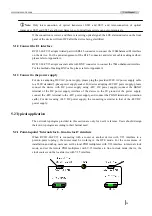
Page 27: ...a 220V standard 3 phase power supply socket For device adopting 48V DC power supply please connect the device with DC power supply using 48V DC power supply connect the BGND terminal of the DC power supply interface of the device to the 0V ground of the power supply connect the 48V terminal to the 48V power supply and connect the PGND terminal to protection earth For device using 24V DC power supp...

Page 28: ...remote DTE device following the clock of local DTE device that is the TX CLOCK of local DTE serves as the internal clock source users can set the clock of local PDH multiplexer with V 35 device to V 35 terminal clock mode and set the clock of remote PDH multiplexer with V 35 interface to line in clock mode ...

Page 29: ...ment query The indicator status of remote RC831 60 FV35 can be viewed on the network management platform Also the current configuration status and alarm information of E1 service and V 35 service can be queried on the network management system 6 3 Network management configuration When the RC831 60 FV35 is a remote device the status of all functions set by DIP switches except for the E1 type switch...

Page 30: ...and SDH devices please refer to the user manual of the corresponding device for parameters like E1 interface type definition and impedance 7 1 2 Make sure that the fiber applied matches the optical transceiver of RC831 60 FV35 For RC831 60 FV35 M please use multi mode fiber with SC PC connector For RC831 60 FV35 S1 S2 S3 please use single mode fiber with SC PC connector For RC831 60 FV35 SS13 SS15...

Page 31: ...The device will begin to initialize and self check after electrifying The process will take no more than 10 seconds During the initialization and self checking the optical interface status indicator LOF and E 6 may flicker for one time which is a normal phenomenon The system will begin its normal operation after 10 seconds During normal operation if the optical interface is correctly connected the...

Page 32: ...nd weld the shield of the cable and that of the BNC connector Fix the protection cover at the rear of the connector firmly TX output signal RX input signal 120Ω RJ 45 interface Please use CAT 5 twisted pair cable with RJ 45 connector to connect to the device For the figure of the RJ 45 connector and its pin arrangement please see Figure A 1 and Table A 1 Figure A 1 The pin arrangement of RJ 45 cry...

Page 33: ...www raisecom com User Manual 26 LNote When making cables please adopt shielded cable in preference to meet the electromagnetic compatibility requirements ...

Page 34: ...as well Optical interface indicator E 6 yellow turns ON The bit error rate of the receiving signal at the optical interface exceeds 1E 6 The E 6 alarm may occur when the device is just electrified This is a normal phenomenon and will last at most 10 seconds before the E 6 indicator turns OFF If the E 6 alarm occurs during the normal operation of the device please check whether the optical interfac...

Page 35: ...www raisecom com User Manual 28 Please check whether the E1 cable has been connected properly and whether the TX and RX of the BNC cable are correctly connected ...

Page 36: ...ress 2nd Floor South Building of Rainbow Plaza No 11 Shangdi Information Road Haidian District Beijing Postcode 100085 Tel 86 10 82883305 Fax 86 10 82883056 Email export raisecom com http www raisecom com ...

Reviews: