background image


Contents 


1.


Cautions.............................................................................................................. 1


2.


Overview............................................................................................................. 2


2.1.


Main features ........................................................................................... 2


2.2.


Part number specification......................................................................... 3


2.3.


Dimension ................................................................................................ 3


3.


Parameters ......................................................................................................... 4


3.1.


Basic configuration................................................................................... 4


3.2.


Ethernet interface parameters.................................................................. 4


3.3.


E1 interface parameters........................................................................... 4


3.4.


CONSOLE interface parameters.............................................................. 5


3.5.


SNMP network management interface parameter ................................... 5


3.6.


Power supply ........................................................................................... 5


3.7.


Ambience ................................................................................................. 5


4.


How to use.......................................................................................................... 6


4.1.


Front panel explanation............................................................................ 6


4.2.


Rear panel explanation ............................................................................ 7


5.


Typical application .............................................................................................. 9


6.


Installation & Preparation.................................................................................. 10


6.1.


Preparation before Installation ............................................................... 10


6.2.


Installation.............................................................................................. 10


6.2.1.


Cable preparation.......................................................................... 10


6.2.2.


Connect the fast Ethernet port .......................................................11


6.2.3.


Connect the SNMP network management port ..............................11


6.2.4.


Connect the CONSOLE port ..........................................................11


6.2.5.


Power on........................................................................................11


6.2.6.


Service configuration..................................................................... 12


7.


Q & A ................................................................................................................ 13


8.


Appendix A: How to make CONSOLE cable..................................................... 14


9.


Appendix B: Abbreviations................................................................................ 15


Summary of Contents for RC953-8FE16E1

Page 1: ...RC953 8FE16E1 Inverse Multiplexing Ethernet Gateway User manual Raisecom Technology Co Ltd 06 2006 ...

Page 2: ...6 Power supply 5 3 7 Ambience 5 4 How to use 6 4 1 Front panel explanation 6 4 2 Rear panel explanation 7 5 Typical application 9 6 Installation Preparation 10 6 1 Preparation before Installation 10 6 2 Installation 10 6 2 1 Cable preparation 10 6 2 2 Connect the fast Ethernet port 11 6 2 3 Connect the SNMP network management port 11 6 2 4 Connect the CONSOLE port 11 6 2 5 Power on 11 6 2 6 Servic...

Page 3: ...ed device that has precise elements please avoid violent shakes and impacts and do not disassemble or maintain the device yourself If it is required please do it under the guide of our technical staff following in the steps of anti static Please contact us if there is any need There must be grounding protection for the sake of safety do not disassemble the device yourself we regard it as you waive...

Page 4: ...he E1 working mode can be Single E1 Mode and Inverse Multiplexing Mode z Provide 8 fast Ethernet interfaces which support auto negotiation auto MDI MDIX 10M 100M half full duplex and IEEE802 3x flow control z HDLC over E1 encapsulation z In single E1 mode Support both framed and unframed E1 mode Only one E1 link in each transmission channel With RC952 in remote sites in hub and spoke topology z In...

Page 5: ...n be installed in 19 rack z Redundant power supply z Power consumption 20W at maximum load z Working temperature 5 50 2 2 Part number specification Part number RC953 A B C 8FE16E1 BL AC Blank DC RC953 inverse multiplexing Ethernet gateway A field 8FE16E1 indicates there are 8 fast Ethernet ports and 16 E1 ports B field E1 connector type BL or blank Blank 75ohm unbalanced BNC connector BL 120ohm ba...

Page 6: ...Line coding HDB3 z Input impedance 75ohm unbalanced z Electric characteristic ITU T G 703 compliant z Frame structure ITU T G 704 compliant z Jitter ITU T G 823 compliant z In single E1 mode E1 interface supports both framed and unframed E1 mode and can be configured through software unframed mode by default In framed E1 mode support N 64k sub rate access and FAS PCM31 without CRC4 FAS CRC4 PCM31 ...

Page 7: ...on z Traffic counter provides an effective E1 link monitoring by statistics collection of Rx TX total and error packets amount on E1 port z 4M Bytes buffer for each Ethernet port to avoid packet loss 3 4 CONSOLE interface parameters Connector type RJ 45 RS232 compliant Rate 9600bps 3 5 SNMP network management interface parameter Utilize one of the 8 fast Ethernet ports please refer to chapter 3 2 ...

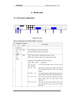
Page 8: ...tes the second power supply works normally Explanation of PWR PWR1and PWR2 combination PWR PWR1 PWR2 Explanation ON ON ON The two power supply modules and main circuit works normally ON ON OFF The first power supply works normally the second works abnormally and the main circuit works normally ON OFF ON The first power supply works abnormally the second works normally and the main circuit works no...

Page 9: ...oss of Signal local Middle LAL local general alarm including AIS alarm indication signal LOF loss of frame CRC cyclic redundancy check Bottom RAL remote general alarm including LOS AIS LOF CRC note when both LOS and LAL are ON at the same time this indicates GID alarm 7 1 8 E1 connector DB37 connector which connects with special cable 8 9 16 E1 indicator Red Each E1 circuit has three indicators fr...

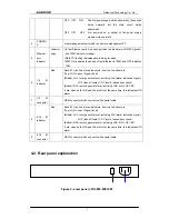
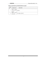
Page 10: ...Raisecom Technology Co Ltd 8 Table 4 2 explanation of RC953 8FE16E1 rear panel Numb er Explanation Description 1 Power supply switch for the device ON OFF 2 Power supply connector Two types AC and DC ...

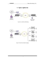
Page 11: ...Raisecom Technology Co Ltd 9 5 Typical application Figure 5 1 point to point topology Figure 5 2 point to multi point topology ...

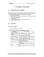
Page 12: ...cables need to be prepared Table 6 1 Cable specification for RC953 8FE16E1 connectors Connector Cable specification 10 100Mbps Electrical Ethernet connector SNMP management connector Cat 5 100Base T UTP and the maximum length is 100m prepared by customers Connector cable for E1 the first 8 E1 utilize one DB37 connector and the second 8 E1 utilize one DB37 connector Please order the 2 cables separa...

Page 13: ...ent PC and one end of the cable with the fast Ethernet port of RC953 8FE16E1 The LNK ACT indicator will be ON after correct connection 6 2 4 Connect the CONSOLE port Connect the RJ 45 connector of CONSOLE cable with the CONSOLE port on the front panel Connect the DB9 connector of CONSOLE cable with the PC serial port Start the HyperTerminal program and configure the COM port properties as follows ...

Page 14: ...her electric level cable Make sure no reverse connection or no short circuited and then turn on power When Power Supply is turned on the PWR indicator should be ON 6 2 6 Service configuration Please refer to the command notebook and configuration guide of RC953 8FE16E1 for the service configuration ...

Page 15: ...e second one works abnormally but the main circuit works abnormally OFF OFF ON The first power supply works abnormally the second one works normally but the main circuit works abnormally OFF OFF OFF Not powered on or neither of the power supply module works normally E1 LOS indicator is ON Answer Loss of receiving signal occurs at e1 port Check whether E1 cable is connected correctly if there is st...

Page 16: ...ix A How to make CONSOLE cable Pin definitions RJ45 pins Function DS9 pins 1 NC 2 DSR 6 3 RxD 3 4 GND 5 5 GND 5 6 TxD 2 7 DTR 4 8 NC indicates the relative RJ45 pin is not connected NC DB9 pins which are not in the list are not connected NC ...

Page 17: ...Raisecom Technology Co Ltd 15 9 Appendix B Abbreviations EoPDH Ethernet over PDH PDH Pseudo synchronous Digital Hierarchy ...

Page 18: ...Raisecom Technology Co Ltd 16 2006 Raisecom Technology Co Ltd All trademarks are the property of their respective owners Technical information may be subject to change without prior notification ...

Reviews: