6
06.14
Josef Kihlberg a.560PN22
5
INITIAL OPERATION
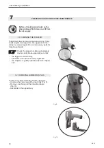
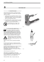
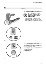
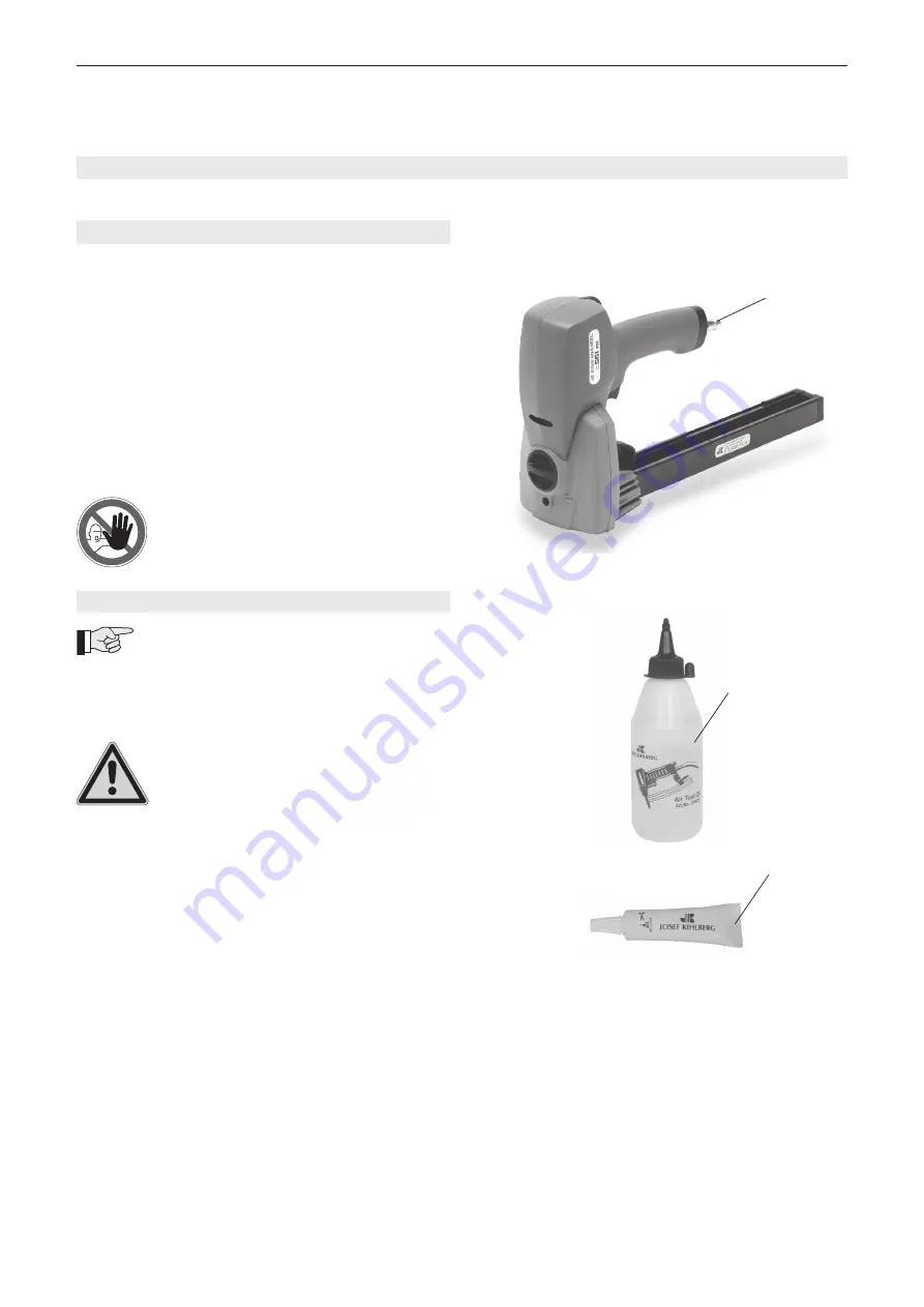
Fig. 2
5.1
INSTALLATION
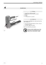
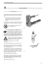
The top stapler is delivered without the compressed
air nipple assembled. Assemble the nipple as follow-
ing:
1. Take the stapler out of the box. Check that the
nipple is the correct brand and fits your air sys
-
tem. Put sealing compound at the threadle.
(Fig. 2/1).
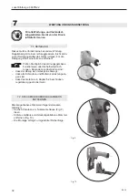
Install compress air nipple manually until a resistance
is perceptible. Use hexagon ring spanner to tighten 1
1/2 turn..
Lay the compressed air hose so there is
no risk of tripping over it.
1
5.2
AIR CONNECTION / LUBRICATION
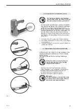
Properly prepared compressed air is essen-
tial for trouble free operation of the stapler.
This can only be ensured by a reliably functioning
maintenance unit, consisting of water separator, pres-
sure reducing valve with pressure gauge. The internal
diameter of the pipe should be at least 10 mm (
3
/
8
“).
Never exceed the maximum permitted air
pressure of 7 bar (102 psi). The maximum
supply pressure is 7 bar (102 psi).
Adjust the working pressure to 5,0–6,0 Bar
(73–87 psi).
A low air pressure will give low maintenance costs!
The stapler and the hose must have a coupling which
automatically bleeds all air pressure from the stapler
when it is disconnected.
The stapler needs a small amount of lubricating oil in
the nipple each day or approx. 10 drops once a week
to ensure safe functioning and endurance. For high
frequency stapling we recommend oil mist lubricator.
Please contact our agent for advice.
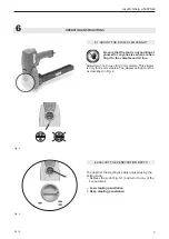
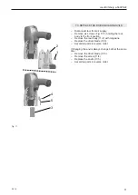
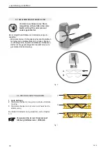
733007 Lubrication oil 0.2 dl. (Fig.3/1)
Sliding parts are greased, with Dow Corning grease
MS 4 Silicon Compound, at the factory. We recom-
mend use this grease on moving parts if they have
been cleaned or replaced.
184943 Tube of MS 4. (Fig. 3/2)
733007
184943
Fig. 3
1
2


