background image

Documentation Center

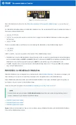
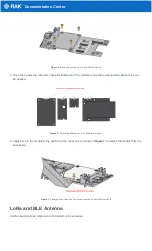
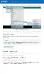
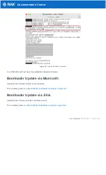
Figure 2: WisBlock Base exposed pins

More information can be found on the 

official documentation of the specific WisBlock Base  

you used in your

project.

For RAK5005-O WisBlock Base with RAK4631 WisBlock Core, the accessible GPIO pins are defined as follows in
the Arduino IDE and Platform IO:

WB_IO1

 for IO1 pin

WB_IO2

 for IO2 pin (Also used to control the 3.3 V supply of some WisBlock Modules to achieve low-power

IoT devices.)

WB_A0

 for AIN

There are usable LEDs as well that can be controlled by the RAK4631 on the WisBlock Base board:

LED_GREEN

LED_BLUE

UART1 and I2C_1 are also exposed on the header of the WisBlock Base board.

RAK4631 has a native USB peripheral onboard (Serial), which is used for programming and Serial debugging
and two usable hardware UART1 and UART2 (Serial 1 and Serial 2). UART1 is accessible to WisBlock Slot A,
WisBlock IO slot, and the exposed header pins. UART2 is accessible only on the WisBlock IO slot.
The I2C_1 header pins are as well shared to the WisBlock Base Slots A to D. The second I2C_2 is available
only on the WisBlock IO slot.

RAK4631 to WisBlock Modules

RAK4631 WisBlock Core is designed to be interfaced with other 

WisBlock Modules  

like sensors, displays, and

other interfaces. You need to connect these modules to the compatible slots on the WisBlock Base.

Each WisBlock Modules that will be used with RAK4631 WisBlock Core have a dedicated quick start guide you
can follow on how to connect to the WisBlock Base.

Listed are the quick start guide of some 

WisBlock modules you can buy from our store  
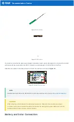
:

📝

 NOTE

The listed links are just examples. All WisBlock Modules have their own quick start guide that you can
use as a reference to get started on specific modules.

RAK1901 Quick Start Guide
RAK1902 Quick Start Guide
RAK1903 Quick Start Guide

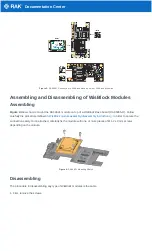
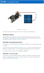
Figure 3 shows an illustration on how you can combine various WisBlock Modules with the RAK4631 WisBlock
Core via the WisBlock Base board.

Summary of Contents for 4631

Page 1: ...dules already included on the kit like sensors IO and other interfaces WisBlock Connected Box This is like the WisBlock Kit but cheaper because some modules and peripherals are not included Excluded p...

Page 2: ...he RAK4631 will not work without a WisBlock Base board The WisBlock Base provides a USB connection for programming the RAK4631 It also provides a power source and various interfaces to RAK4631 so that...

Page 3: ...lot and the exposed header pins UART2 is accessible only on the WisBlock IO slot The I2C_1 header pins are as well shared to the WisBlock Base Slots A to D The second I2C_2 is available only on the Wi...

Page 4: ...sBlock Base board RAK5005 O Follow carefully the procedure defined in WisBlock module assembly disassembly instructions in order to secure the connection safely Once attached carefully fix the module...

Page 5: ...ion where force can be applied Figure 6 Detaching silkscreen on the WisBlock module 3 Apply force to the module at the position of the connector as shown in Figure 7 to detach the module from the base...

Page 6: ...abel on its sticker where to connect the antennas as shown in Figure 10 Figure 10 RAK4631 Antenna Label NOTE Detailed information about the RAK4631 BLE and LoRa antenna can be found on the antenna dat...

Page 7: ...to use other types of batteries with the system unless you know what you are doing If a non rechargeable battery is used it has to be unplugged first before connecting the USB cable to the USB port o...

Page 8: ...quickly build your IoT device with less friction example codes for RAK4631 to be used on all WisBlock Modules are provided You can access the codes on the WisBlock Example code repository The example...

Page 9: ...e just examples All WisBlock Modules have their own quick start guide that you can use as a reference to get started on specific modules RAK1901 Quick Start Guide RAK1902 Quick Start Guide RAK1903 Qui...

Page 10: ...this to a region that is applicable to you like LORAMAC_REGION_US915 LORAMAC_REGION_AU915 etc 2 Setup the activation method Default is OTAA To configure the device to ABP you need to make this boolean...

Page 11: ...it ilat variable is formatted to a 4 byte size array DeviceClass_t g_CurrentClass CLASS_A uint8_t nodeDeviceEUI 8 0x88 0x88 0x88 0x88 0x88 0x88 0x33 0x33 uint8_t nodeAppEUI 8 0xB8 0x27 0xEB 0xFF 0xFE...

Page 12: ...the data must be in the main loop The same with the transmission function the receiving event handler should be short as well All processing of the received data should be in the main loop Uploading t...

Page 13: ...an open source community project that uses LoRa technology to make a long range mesh communicator You need to download the latest Meshtastic firmware and upload it to your RAK4631 to make it compatib...

Page 14: ...ick the reset button on the WisBlock Base There will be a new drive named RAK4631 that will be shown on your folder explorer Inside this drive there will be a text file named INFO_UF2 TXT as shown in...

Page 15: ...pository Once you downloaded these files you need to put them in the same directory folder on your computer For simplicity this guide will assume the files are in C drive Figure 20 Adafruit nrfutil an...

Page 16: ...o the PC via USB Now use the dmesg command to display system information and check if the USB device has been recognized by Linux If the RAK4631 USB device is recognized a listing for the device simil...

Page 17: ...hod download adafruit nrfutil macos and make it executable Usually the adafruit nrfutil macos file will go to the downloads folder The next step after downloading the file is to open the terminal and...

Page 18: ...er Update via Bluetooth Updating the firmware via BLE is also possible The complete guide is on the RAK4631 Bootloader repository using BLE Bootloader Update via Jlink Updating the firmware via Jlink...

Reviews: