background image

16

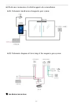
Three sets of lines shall be embedded in host equipment (reserved line is 10cm long)

(1)

The 12V power supply cable RVV2x1.0 standard and above, one end at the host equipment, the
other end to the 220V or 22-well outlet at the top of the shift door, install the 12V2A factory 12V
adapter, the adapter 220V power cable directly plugged into the 220V power 2-well socket.

(2)

Door opening control line RVV2x0.5 standard and above, one end at the host equipment, and the
other end to the original access control special power supply or door removal entry control
controller, to connect their door signal interface during installation.

(3)

Super five types of network wire 8x0.5 anaerobic copper standard and above, one end at the host
equipment, the other end to the weak power room switch connected to the Internet. In special
circumstances, if the wired network is difficult, the wireless network at the door is also very stable,
so wireless can be considered.

7.1.2

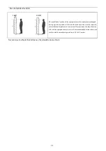
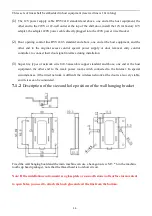
Description of the size and hole position of the wall hanging bracket

Fixed the wall hanging board and the main machine can use a hexagon screw M 3 * 6 in the machine

tooth cup head (package), note that the thread head is not short circuit.

Note: If the installation environment is a glass plate or a smooth stone wall surface inconvenient

to open holes, you need to attach the back glue and exit the line from the bottom;

Summary of Contents for F6

Page 1: ...1 Facial Recognition Device Product model F6 Product version V1 0 Please read this instruction carefully before use...

Page 2: ...d magnetic door installation 10 6 2 1 Schematic installation of magnetic gate system 10 6 2 2 Schematic diagram of the wiring of the magnetic gate system 10 Installation instructions 10 7 1 Wall mount...

Page 3: ...without user cooperation to achieve live detection dynamic face recognition to provide users with the use environment of the safety area The product is based on 200W RGB 200W IR binocular camera supp...

Page 4: ...on 5 communication Live detection 8 inch ultra clear touch screen sound interaction prompt 6 environment Super strong environmental adaptability low light and strong reverse light all have a very good...

Page 5: ...800 1280 touch screen support Human temperature measurement module apolegamy Test accuracy 0 1 test error 0 5 Temperature measurement distance the recommended use distance is 50cm Operating temperatur...

Page 6: ...key Upgrade key source adapter DC12V 2A power supply Environmen tal requirement s working temperature 20 60 Operating humidity 20 90 in no condensation drop state static electricity ESD IEC61000 4 2 L...

Page 7: ...ent quan tity 1 main engine 1 2 Support kit 1 3 Power adapter 1 4 Sunshades Optional 1 5 Install the screw bag 1 6 Product warranty card 1 Product structure Part serial number function declaration Fi...

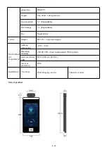
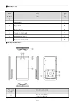
Page 8: ...7 16 RGB camera...

Page 9: ...ain internet access RJ45 Support for 10 100Mbps electric relay NC COM NO Relys are often closed public regular The door lock power supply is generally being connected to the COM end Depending on the d...

Page 10: ...8 16 reset Upgrate GND Support for manual reset upgrade Serial RS485 TX RS485 RX Support for serial port RS485...

Page 11: ...e with 26bit 34bit protocol support Enter the power supply GND 12V Power Supply Input 12V DC USB USB_HOST 4P External reserved USB interface peripheral USBA 2 0_OTG Equipment upgrade debugging U disk...

Page 12: ...Reference instructions for field magnetic door installation 6 2 1 Schematic installation of magnetic gate system 6 2 2 Schematic diagram of the wiring of the magnetic gate system Installation instruc...

Page 13: ...rature or low temperature high humidity strong backlight vibration radiation and chemical corrosion matters need attention Before opening the main screen equipment tear off the screen protector to avo...

Page 14: ...is really required the installation height must be consistent If inconsistent the identification effect of the equipment may be worse The recommended distance between the face and the machine registr...

Page 15: ...consistent The distance is too close It s too far away 7 1 Wall mounted installation instructions 7 1 1 installation site On a wall about 130cm from the ground start the first row of holes using 6mm d...

Page 16: ...oor signal interface during installation 3 Super five types of network wire 8x0 5 anaerobic copper standard and above one end at the host equipment the other end to the weak power room switch connecte...

Page 17: ...with screws Step 4 Lock Tighten the host to the wall mount with screws Filire adjust wiring length until the equipment can be buckled into wall mount fittings Declaration of toxic and harmful substan...

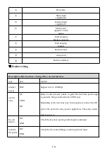
Page 18: ...18 This table is prepared according to the provisions of SJ T11364...

Page 19: ...our products to ensure the interests of the users any user who buys the quality products can contact the local dealer or special maintenance station with the invoice and warranty card Warranty Instru...

Page 20: ...20...

Reviews: