background image

19

O

It indicates that the content of the hazardous material in all homogeneous materials of the

component is below the limit requirements of GB / T26572

X

It means that the content of the hazardous substance in at least a homogeneous material of the

component exceeds the limit requirements specified in GB / T26572

This identification period refers to the period (ten years), harmful substances in electronic

and electrical products will not leak or mutation under normal use conditions, users use

the electronic information products will not cause serious pollution to the environment or

serious damage to their personal and property.

This product meets the RoHS environmental protection requirements: there is no

international mature technology to replace or reduce the lead content in electronic,

ceramic optical glass, steel and copper alloys.

Product warranty

Thank you for purchasing our products, to ensure the interests of the users, any user who buys the quality

products can contact the local dealer or special maintenance station with the invoice and warranty card.

Warranty Instructions:
1. Within one year from the date of purchase, in the case of normal use, the company shall provide free

warranty parts replacement and other services according to the fault situation;

2. Warranty card and purchase invoice are the vouchers for the company to provide after-sales

service to customers. This card must be filled in the following form in detail, and can only be valid

with the official seal of the dealer;
3. Under one of the following circumstances, warranty service is not implemented, and fee maintenance is
required,

(1)

Over the validity period of the warranty;

(2)

Damage by failure to use, maintain or keep improperly as required by the product instructions;

(3)

Fault and damage caused by the disassembly, repair and modification of the product without the

permission of the Company;

(4)

Machine failure or damage caused by force majeure;

(5)

Damaged parts and random accessories.

Summary of Contents for F6

Page 1: ...1 Facial Recognition Device Product model F6 Product version V1 0 Please read this instruction carefully before use...

Page 2: ...d magnetic door installation 10 6 2 1 Schematic installation of magnetic gate system 10 6 2 2 Schematic diagram of the wiring of the magnetic gate system 10 Installation instructions 10 7 1 Wall mount...

Page 3: ...without user cooperation to achieve live detection dynamic face recognition to provide users with the use environment of the safety area The product is based on 200W RGB 200W IR binocular camera supp...

Page 4: ...on 5 communication Live detection 8 inch ultra clear touch screen sound interaction prompt 6 environment Super strong environmental adaptability low light and strong reverse light all have a very good...

Page 5: ...800 1280 touch screen support Human temperature measurement module apolegamy Test accuracy 0 1 test error 0 5 Temperature measurement distance the recommended use distance is 50cm Operating temperatur...

Page 6: ...key Upgrade key source adapter DC12V 2A power supply Environmen tal requirement s working temperature 20 60 Operating humidity 20 90 in no condensation drop state static electricity ESD IEC61000 4 2 L...

Page 7: ...ent quan tity 1 main engine 1 2 Support kit 1 3 Power adapter 1 4 Sunshades Optional 1 5 Install the screw bag 1 6 Product warranty card 1 Product structure Part serial number function declaration Fi...

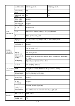
Page 8: ...7 16 RGB camera...

Page 9: ...ain internet access RJ45 Support for 10 100Mbps electric relay NC COM NO Relys are often closed public regular The door lock power supply is generally being connected to the COM end Depending on the d...

Page 10: ...8 16 reset Upgrate GND Support for manual reset upgrade Serial RS485 TX RS485 RX Support for serial port RS485...

Page 11: ...e with 26bit 34bit protocol support Enter the power supply GND 12V Power Supply Input 12V DC USB USB_HOST 4P External reserved USB interface peripheral USBA 2 0_OTG Equipment upgrade debugging U disk...

Page 12: ...Reference instructions for field magnetic door installation 6 2 1 Schematic installation of magnetic gate system 6 2 2 Schematic diagram of the wiring of the magnetic gate system Installation instruc...

Page 13: ...rature or low temperature high humidity strong backlight vibration radiation and chemical corrosion matters need attention Before opening the main screen equipment tear off the screen protector to avo...

Page 14: ...is really required the installation height must be consistent If inconsistent the identification effect of the equipment may be worse The recommended distance between the face and the machine registr...

Page 15: ...consistent The distance is too close It s too far away 7 1 Wall mounted installation instructions 7 1 1 installation site On a wall about 130cm from the ground start the first row of holes using 6mm d...

Page 16: ...oor signal interface during installation 3 Super five types of network wire 8x0 5 anaerobic copper standard and above one end at the host equipment the other end to the weak power room switch connecte...

Page 17: ...with screws Step 4 Lock Tighten the host to the wall mount with screws Filire adjust wiring length until the equipment can be buckled into wall mount fittings Declaration of toxic and harmful substan...

Page 18: ...18 This table is prepared according to the provisions of SJ T11364...

Page 19: ...our products to ensure the interests of the users any user who buys the quality products can contact the local dealer or special maintenance station with the invoice and warranty card Warranty Instru...

Page 20: ...20...

Reviews: