DISASSEMBLY OF WHEEL DRIVE
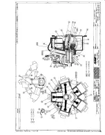
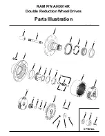
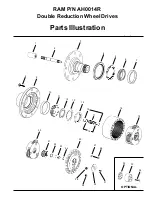
Refer to Parts Illustration
STEP 1
Slide the coupling (1) from splines on input shaft (2).
STEP 2
Position the assembly upright on face of spindle (3).
STEP 3
Remove the disengage cover (30) if necessary.
STEP 4
Remove twenty-four bolts (26) and flat washers (27) and the large cover (25) from the unit. The thrust
washer (22) and the disengage plunger (23) usually remain attached to the large cover (25) when it is
removed. Remove thrust washer (22), disengage plunger (23) and “O” ring (24) from the large cover
(25).
STEP 5
Remove primary sun gear (21) from end of input shaft (2).
STEP 6
Remove the primary carrier assembly (20).
STEP 7
Remove the secondary carrier assembly (19). It may be necessary to remove the ring gear (18) first, if
difficulty is encountered removing the carrier.
STEP 8
Remove the input shaft (2) from spindle (3). Remove the retaining rings (15), washer (16), and
disengage spring (17) from input shaft (2) only if replacement is required.
STEP 9
If not previously removed (see step 7) remove ring gear (18) from hub (9). It may be necessary to strike
ring gear (18) with a rubber mallet to loosen from hub (9).
STEP 10
One tab of lock washer (13) will be engaged in the slot of bearing nut (14); bend back to release.
Remove the bearing nut (14), lock washer (13) and thrust washer (12). Note: A special locknut wrench,
593RR, required for the removal of the bearing locknut. Contact RAM Winch & Hoist for procurement
of wrench and other service tools.
STEP 11
Bolt spindle drive tool, 598FF, to hub (9). Drive spindle (93) from hub (9) by turning bolt in center of
spindle drive tool. Care should be taken to avoid damaging splines and threads on spindle. Note:
Bearing cone (11) has been designed with a press fit with respect to spindle (3). Considerable force will
be required to remove cone from spindle.
STEP 12
Remove the boot seal (4) and oil seal (5) and bearing cones (6 & 11) from hub (9). Inspect bearing
cups (7 & 10) in position and remove only if replacement is required.
Summary of Contents for K5UR120ML-AM1G Series
Page 1: ...MODEL K5UR120ML XX AM1G UTILITY AND MANLIFTER AIR WINCH ...
Page 2: ......
Page 3: ......
Page 4: ......
Page 6: ......
Page 7: ......
Page 8: ......
Page 9: ......
Page 10: ......
Page 11: ......
Page 12: ......
Page 13: ......
Page 14: ......
Page 15: ......
Page 16: ......
Page 17: ......
Page 18: ......
Page 20: ......
Page 21: ......
Page 22: ......
Page 23: ......
Page 24: ......
Page 25: ...above ...
Page 26: ......
Page 27: ......
Page 28: ......
Page 29: ......
Page 30: ......
Page 32: ......
Page 33: ......
Page 34: ......
Page 35: ......
Page 36: ......
Page 37: ......
Page 38: ......
Page 39: ......
Page 40: ......
Page 41: ......
Page 43: ......
Page 44: ......
Page 45: ......
Page 46: ...Brake Mount Assembly ...
Page 47: ......
Page 48: ......
Page 49: ......
Page 50: ......
Page 51: ......
Page 52: ......
Page 54: ...K5W 507 PD5 H505A ...
Page 55: ...KD5 A501 Model No AG78301 402790 1M ...
Page 56: ......
Page 57: ...RAM P N AH04414R Double Reduction Wheel Drive SERVICE MANUAL ...
Page 64: ......
Page 68: ......
Page 69: ...Component Data Sheets ...
Page 70: ......
Page 71: ...RAM P N AG35139 Air Cylinder ...
Page 72: ......
Page 73: ...RAM P N AG35139 A Air Cylinder ...
Page 74: ......
Page 75: ...RAM P N LB80045R 1 1 2 LUBRICATOR ...
Page 76: ......
Page 78: ......
Page 79: ...RAM P N LB80040R 1 1 2 FILTER ...
Page 81: ......
Page 82: ......
Page 83: ...RAM P N LB80050 REGULATOR ...
Page 86: ......
Page 87: ...RAM P N AG70252 ...
Page 88: ......
Page 89: ......
Page 90: ...K5UR120ML Air Winch RAM WINCH HOIST 12 05 K5UR120ML Air Winch RAM WINCH HOIST 11 06 ...


