background image

Installation and 

 Operation

Instalación y 

operación

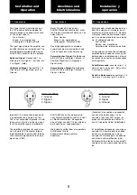
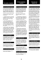
The amplifier can operate on two differ-
ent configurations: DUAL or LINK. The 
connections for the three modes are dif-
ferent. 


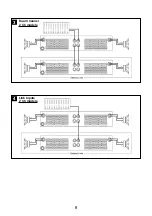
See Figure 


- Set the rear minidips in No-Link posi-

tion (3 and 4 down). 

- Select the chosen Gain (Default set-

ting 32dB). 

- Connect the signal lines to the female 

XLR connectors on all channels. 

- Connect the speakers’ lines to the cor-

responding Speakon on the amp 
respecting the polarity. 

- Use the level control knob on the front 

panel to adjust each channel indepen-
dently. 

- Each signalling LED group will show 

its corresponding channel status. 


See Figure 


- Set the rear minidips in Link position 

(3 and 4 up). 

- Operate as Dual Channel Mode with 

the signal input linked to another adja-
cent channel. 

4

3.1.2 LINK Channel Mode

3

3.1.1 DUAL Channel Mode

Existen dos modos de funcionamiento 
posibles del amplificador: Dual y Link. 
Las conexiones en cada caso son dife-
rentes. 


Ver figura 


- Coloque los minidips traseros en posi-

ción No-Link (3 y 4 abajo). 

- Seleccione la ganancia elegida (32dB 

por defecto). 

- Conecte las señales de entrada de 

todos los canales por sus respectivos 
XLR hembra. 

- Conecte los altavoces a los Speakon 

de cada canal, respetando polaridad. 

- Utilice el control de nivel de cada 

canal para controlar independiente-
mente los niveles de salida  

- Los LEDs de señalización indicaran la 

situación independientemente de cada 
canal. 


Ver figura 


- Coloque los minidips traseros en posi-

ción Link (3 y 4 arriba). 

- Opere como modo Dual con la señal 

de entrada linkada a otro canal adya-
cente. 

3.1.1 Modo Dual (Stereo)

3

3.1.2 Modo LINK

4

Es gibt zwei Funktionsmöglichkeiten 
dieser Endstufe: Dual und Link. Die 
Anschlüsse sind in den drei Fällen 
unterschiedlich. 


Siehe Fig. 


- Stellen Sie die hinteren Minidips in die 

No-Link-Position (3 und 4 nach unten). 

- Bitte wählen Sie den 

Eingangspegelwert (Werkseinstellung 
32 dB). 

- Schließen Sie alle Eingangssignale an 

ihre entsprechenden XLR-Buchsen. 

- Schließen Sie die Lautsprecher an die 

entsprechenden Speakon an, bitte die 
Polarität ist beachten.  

- Benutzen Sie die Lautstärkeregelung 

der entsprechenden Kanäle um den 
gewünschten Lautstärkepegel zu errei-
chen. 

- Die LED-Anzeigen geben den Status 

der beiden Kanäle an. 


Siehe Fig. 


- Stellen Sie die hinteren Minidips in die 
Link-Position (3 und 4 nach oben). 
- Gehen Sie wie im Dual-Channel-

Modus vor, wobei das Eingangssignal 
mit einem angrenzenden Kanal ver-
bunden ist. 

4

3.1.2 LINK Kanalmodus

3

3.1.1 DUAL Kanalmodus

7

Anschluss und 

Inbetriebnahme

Summary of Contents for XTR-18K

Page 1: ...ON MANUAL BEDIENUNGSANLEITUNG MANUAL DE EMPLEO P 4816 599 QXPDRFDoc 9 19 2019 by C E Studio 2 s l Spain EEC http www ramaudio com e mail support ramaudio com Professional Power Amplifiers XTR Series 1...

Page 2: ...sonal Es handelt sich um ein Ger t der Klasse I IMPORTANT Clean the front panel filters regularly Extract the filters removing the front panel grid unscrewing the screews pla ced at the sides of the g...

Page 3: ...2 s l All other names are trademarks of their respective companies 0 Sicherheitshinweise 1 Allgemeine Anweisungen 1 1 Einleitung 1 2 Allgemeine Eigenschaften 2 Lokalisierung der Funktionen 2 1 Frontpl...

Page 4: ...canales preparados para soportar las extremadamente exigentes aplicaciones del mundo del touring Para esto los amplificadores de la serie XTR han sido dise ados con una sobredimensionada fuente de ali...

Page 5: ...IGNAL Wachanzeige des einge henden Signals ICL Die LED zeigt an dass der Intelligent Cliplimiter arbeitet siehe Seite 13 Beleuchteter Hauptstromschalter Position I Schaltet die Endstufe ein Position O...

Page 6: ...o connect the amplifier to the mains network The color code is Blue Neutral Brown Live single phase Yellow green Protective Earth Gain Selection Minidips Gain Selection Minidips 1 and 2 Three position...

Page 7: ...sse 2 Signal 3 Masse ACHTUNG Wenn Sie ein asymetris ches Signal anschlie en und Pin 3 nicht an Masse anschlie en erzeugt dies einen Verlust von 6dB 1 4 der Leistung der Endstufe am Ausgangssignal Die...

Page 8: ...bra Conecte los altavoces a los Speakon de cada canal respetando polaridad Utilice el control de nivel de cada canal para controlar independiente mente los niveles de salida Los LEDs de se alizaci n i...

Page 9: ...3 4 Dual Channel 2 Ch models 2 Ch models 8 Link Inputs...

Page 10: ...ird so lange gehemmt bis die Enstufe voll funk tionsbereit ist Die Innentemperatur steigt aufgrund ung nstiger Arbeitsbedingungen nahe des Grenzwertes bei dem die automa tische Ausschaltefunktion akti...

Page 11: ...chlie lich unter Laborbedingungen ein in sinusf rmigen Langzeitsignaltests mit Dummylasten oder in langanhaltenden akustischen Feedback Bedingungen Hier greift das PMS System ein um eine Sch digung de...

Page 12: ...0Hz 8 Ohm 500 Crosstalk 20Hz 20kHz 80dB Voltage Gain 32 38 44 dB Sensitivity Rated Power 32 38 44dB Gain 3 9 1 9 1 V 4 7 2 4 1 2 V Signal to Noise Ratio 20Hz 20kHz 116dB 118dB Required AC Mains Operat...

Page 13: ...actured in the EEC by C E Studio 2 s l Pol Ind La Figuera C Rosa de Luxemburgo n 34 46970 Alaquas Valencia SPAIN Phone 34 96 127 30 54 Fax 34 96 127 30 56 http www ramaudio com e mail support ramaudio...

Reviews: