background image

DO   NOT,   UNDER   ANY   CIRCUMSTANCES,   CUT   OR   REMOVE   THE  THIRD

(GROUND) PRONG FROM THIS POER CORD.

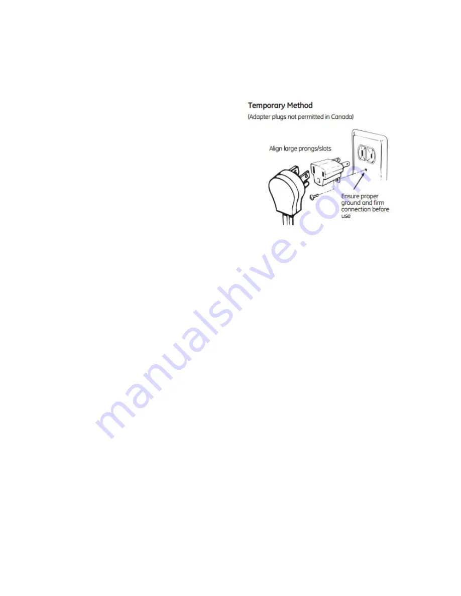
Temporary Method (Adapter plugs not permitted Canada)

CAUTION:  

Attaching   the   adapter   ground

terminal to the wall receptacle cover screw does

not ground the appliance unless the cover screw is

metal,   not   insulated,   and   the   wall   receptacle   is

grounded through the house wiring. The customer

should   have   the   circuit   checked   by   a   qualified

electrician to make sure the receptacle is properly

grounded.

BATTERY IGNITION (Certain models)

If the auto ignition does not work, make sure that the battery, installed at the back of the cooker, 

is not flat and has been installed correctly.

INSTALLING THE BATTERY

Insert a DC1.5V battery into the battery compartment (see below Fig.10, Fig.11) in the cover. 

This battery is the power supply for the electronic ignition of gas burners.

Notes for battery installation or replacement:

• Only use a DC 1.5 Volt battery.
• Check for correct polarity ( label to the side of the battery compartment) the electronic ignition 
is used

Important notes:

• Remove the battery if the cooker is not going to be used for a long time.
• If the battery leaks, replace it immediately.

Avoid touching the leaked liquid and make sure it does not come into contact with clothes or 
other items.
• Clean the battery compartment carefully before installing the new one.
• Note: The battery is a potential source of danger for children. Keep them away.
• Dispose of flat batteries properly.

12

Summary of Contents for GC2-48N

Page 1: ...User Guide Gas Cooktop MODEL GC2 48N GC2 48P GC1 28N GC1 28P GC2 43P GC2 43N GC2 43PB Battery Ignition 1...

Page 2: ...or the gas supplier WARNING Gas leaks cannot always be detected by smell Gas suppliers recommend that you use a gas detector approved by UL or CSA If a gas leak is detected follow the What to do if s...

Page 3: ...be stored on or near surface units Top burner flame size should be adjusted so it does not extend beyond the edge of the cooking utensil IMPORTANT This appliance is designed and manufactured solely fo...

Page 4: ...ase use the Cutting size board cardboard packed in the box to outline cut hole in counter top Clearance between the underneath of unit and any surface below it should be at least 1 inch 30mm If there...

Page 5: ...at a 30 mm clearance be left between the cooker top and the fixture surface Fig 2 Note The adjacent furniture and all materials used in installation must be able to withstand a minimum of 85 C above t...

Page 6: ...heat damage or discoloration at temperatures below 85 C DISCHARGING PRODUCTS OF COMBUSTION Extractor hoods connected directly to the outside should be provided to allow the products of combustion of...

Page 7: ...nd position Position the cooktop in the recess and secure by means of the brackets as shown in fig 6 for 3 or 4 cm thick work top BUILT IN DIMENSION MODEL CUT OUT DIMEN SION Inch GC2 48N 10 5 x18 9 Wx...

Page 8: ...ure you are supplying your cooktop with the type of gas for which it s designed This cooktop is convertible for use on nature or propane gas If you decide to use this cooktop on LP gas conversion must...

Page 9: ...ure is different than that prescribed a pressure regulator must be installed at the source in compliance with national standards government the use of piped gas regulators To complete the conversion f...

Page 10: ...a backup wrench on the regulator fitting to avoid damage When installing the range from the front remove the 90 elbow for easier installation Install male 1 2 or 3 4 flare union adapter to the NPT in...

Page 11: ...on cord However if you still elect to use on extension cord it is absolutely necessary that it be a UL listed 3 wire grounding type appliance extension cord and that the current carrying rotting of th...

Page 12: ...d has been installed correctly INSTALLING THE BATTERY Insert a DC1 5V battery into the battery compartment see below Fig 10 Fig 11 in the cover This battery is the power supply for the electronic igni...

Page 13: ...13...

Page 14: ...ions and also close the gas shut off valve placed on the main gas supply line LIGHTING GAS BURNERS Any film or stickers on the cooktop surface should be removed before use All operations are performed...

Page 15: ...does not necessarily mean that the boiling conditions are reach quicker Table of recommended pans Burner Pan diameter in cm Auxiliary Semi rapid Rapid Triple ring from dia 8 to dia 14 from dia 14 to d...

Page 16: ...re clean to ensure trouble free sparking Stainless steel can be stained if it s in contact with highly calcareous water or aggressive detergents containing phosphorous It is recommended these parts be...

Page 17: ...g burner must be correctly positioned seen fig 7 the burner rib must be entering in their ligament as shown by the arrow The burner correctly positioned must not be able to rotate fig 8 Then position...

Page 18: ...hts around the cooking surface The flame does not stay lighted on the model with the safety device Check to make sure that You press the knob all the way in You keep the knob pressed in long enough to...

Page 19: ...ote Default setting LPG regulator is with a RED bar mark NG regulator is without it 3 Installation Method User to install the external gas hose Threads can be coated with appropriate amount of sealant...

Page 20: ...only DO NOT adjusts the regulator valve body to alter factory setting 5 Warning Regulator valve outlet pressure is set at the factory please do not temper its setting structure Under all circumstances...

Reviews: