background image

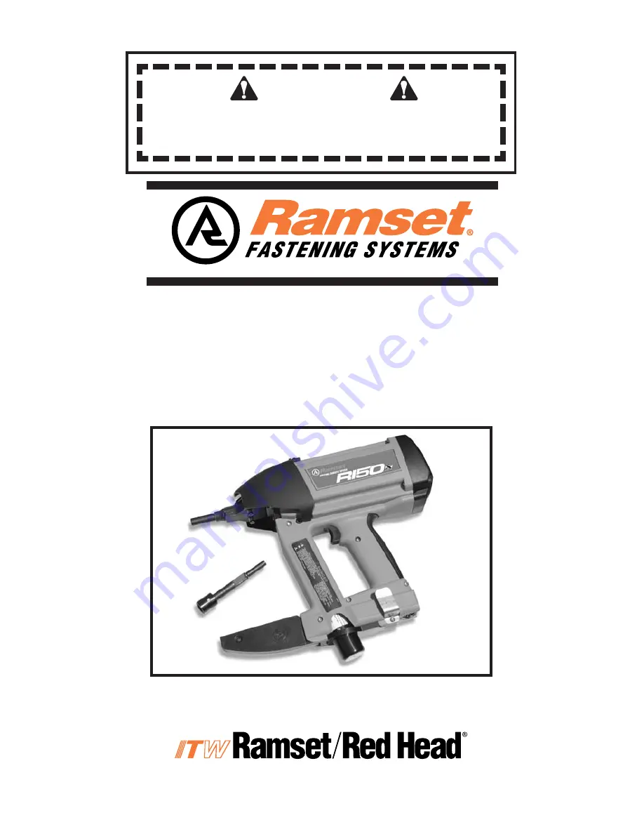
RAMSET R150 TOOL

OPERATOR’S 

SAFETY & OPERATING 

INSTRUCTION MANUAL

DANGER

READ AND OBEY ALL SAFETY AND OPERATING

INSTRUCTIONS BEFORE OPERATING TOOL.

GAS POWERED, LOW VELOCITY

PISTON TYPE  FASTENING TOOL

Summary of Contents for R150

Page 1: ...RAMSET R150TOOL OPERATOR S SAFETY OPERATING INSTRUCTION MANUAL DANGER READ AND OBEY ALL SAFETY AND OPERATING INSTRUCTIONS BEFORE OPERATING TOOL GAS POWERED LOW VELOCITY PISTON TYPE FASTENING TOOL...

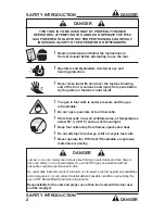
Page 2: ...E THE R150 GAS POWERED TOOL WITHOUT PROPER TRAINING CAN RESULT IN SERIOUS INJURY TO THE OPERATOR OR BYSTANDERS SAFETY INTRODUCTION DANGER 2 Read understand and follow the instructions in the tool manu...

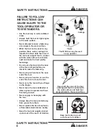
Page 3: ...bility of the base material can result in serious injury to the eyes or other body parts Center Punch Test ALWAYS WEAR SAFETY GOGGLES WHEN PERFORMING THIS TEST 1 Always check the material being fasten...

Page 4: ...s be used in the R150 tool Batteries The battery will become discharged even if the tool is not being used Remove the battery from the tool when the tool is not to be used or put it in the no contact...

Page 5: ...on the battery needs recharged Installing the fuel cell There is a cap located on the rear of the tool handle that covers the fuel cell Twist the cap 1 8 turn clockwise and remove it Insert the fuel c...

Page 6: ...before you intend to make the fastening Never put your hand over the nose end of the tool Never put your hand on or over the end of the tool to close the tool Never carry the tool with your finger on...

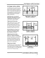
Page 7: ...e thickness should be at least three times the intended penetration depth into the concrete Driving fasteners too close to an edge or too close to each other can cause the concrete edge to fail or fas...

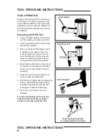
Page 8: ...zle bushing of the tool Do not force the fastener into the tool such that you cause the muzzle bushing to be pushed up into the tool body 4 Note that the LED light on the side of the handle is a solid...

Page 9: ...the tool Replace 1 Orient the Work Contact Element so that the notched or flat portion is toward the back or the tool 2 Firmly push the Work Contact Element up into the nose piece 3 Slightly twist the...

Page 10: ...PARTS SCHEMATIC 10 PARTS SCHEMATIC R150 TOOL SCHEMATIC...

Page 11: ...R150 TOOL SCHEMATIC continued PARTS SCHEMATIC 11 PARTS SCHEMATIC...

Page 12: ...AINING RING 13 404601 HEAD SWITCH 14 B0078 CYLINDER HEAD 15 403992 O RING CYLINDER HEAD 16 403167 FAN BLADE 17 B0044 CAGE ASSEMBLY 18 EM150300A SHEAR BLOCK PLATE KIT INCLUDES PLATE AND TWO M5 SCREWS 1...

Page 13: ...TCH ASSEMBLY 42 404385 LIGHT CONDUIT 43 B0098 SPARK UNIT ASSEMBLY MEFI 45 010422 EFI JUNCTION BOARD 46 333450 TRIGGER ASSEMBLY 47 333460A FEED ASSEMBLY INCLUDES FUEL FEED ASSEMBLY FEED TUBE 49 333480A...

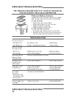
Page 14: ...an is on but the tool does not fire LED is red Battery power is too low Recharge battery LED is green Fuel cell is exhausted Put in new fuel cell Fan stops after the Call your local distributor for se...

Page 15: ...ted to misuse abuse accidental or intentional damage use with fasteners fuel battery or battery chargers not meeting ITW Ramset Red Head specification size or quality improperly maintained repaired wi...

Page 16: ...Road 739 Roble Road Commerce CA 90040 Paris KY 40361 Allentown PA 18109 Phone 800 368 9724 CA only Phone 800 726 7386 Phone 800 266 9723 Phone 800 227 1823 Fax 800 816 6673 Fax 610 266 0962 Fax 800 2...

Reviews: