background image

SERVICING / TROUBLESHOOTING

SERVICING / TROUBLESHOOTING

19

SYMPTOM 

POSSIBLE PROBLEMS   SERVICE

Preparing Tool for Operation—Battery/Charger Problems 

— Battery Cell does not    — Inoperative indicator    — Try Battery Cell in tool after 3 hours  

  appear to accept  

  lights on charger 

  on charge cycle. If tool LED is 

  charge. Green charger     

  green, charger lights are not 

  light does not come on     

  working properly. Replace charger, 


  or monitor charging time to ensure  


  Battery Cell has adequate time for  


  recharging. It’s normal for Battery  


  to feel warm after properly charging. 


— Battery Cell damaged    — Replace Battery Cell 


  or cycle life exhausted


— Damaged charger 

— Discontinue use immediately and  


  unplug from power source. Replace  


  charger and tag or dispose of  


  charger to prevent accidental  


  reuse or connection to power source.

— Flashing lights on   

— Damaged Battery Cell  — Replace Battery 

  charger base unit 

— Battery Completely  

— Allow battery to charge for  


  Drained 

  5 minutes

Normal Stage of Operation 

— Fan does not run 

— Battery in off position  — Fully insert Battery


—tool LED is off


— Battery Cell is  

— Charge Battery Cell according to  


  not charged 

  Operating Manual.  


— Battery terminals or  

— Clean Battery Cell terminals.  


  battery contacts are 

  Battery Cell contacts as required. 


  oily, dirty, or corroded   

— Fan does not run,  

— Battery Cell is  

— Charge Battery Cell 

  or runs slower than 

  discharged 

  normal—tool LED is red
— Fan does not run,  

— Possible electronics 

— Remove, reinsert the Battery 

  tool LED flashes  

  error 

    Contact Authorized Ramset  

  red/green 


  Distributor Sales Representative 


  for service.

Pre-Combustion/Combustion Stage of Operation 

— Work Contacting   

 —Work Contacting  

— Remove and inspect Work Contact 

  Element does not  

  Element is bent, or 

  Element. Repair or replace Work  

  depress fully—tool  

  build-up of debris in 

  Contact Element as required. 

  does not operate  

  nose restricts operation   


— O-Ring pinched 

— Contact Authorized Ramset   


  Distributor Sales Representative  


  for service.

(For T3 Magazine tool only)

  — Tool is out of fasteners  — Add fastener strip

— Tool will not cycle—fan — Fuel Cell is empty 

— Replace Fuel Cell 

  runs, LED is green
   

— Spark does not occur.  — Contact Authorized Ramset  


  Distributor Sales Representative  


  for service.  

Summary of Contents for T3MAG

Page 1: ...HOT T3 MAGAZINE OPERATOR S SAFETY OPERATING INSTRUCTION MANUAL DANGER READ AND OBEY ALL SAFETY AND OPERATING INSTRUCTIONS BEFORE OPERATING TOOL GAS POWERED LOW VELOCITY PISTON TYPE FASTENING TOOL T3SS...

Page 2: ...recharge refill or recycle fuel cells Never operate the T3 tool if flammable or explosive materials are nearby Just as no one can merely read a book about driving an automobile and then hope to drive...

Page 3: ...bility of the base material can result in serious injury to the eyes or other body parts Center Punch Test ALWAYS WEAR SAFETY GOGGLES WHEN PERFORMING THIS TEST 1 Always check the material being fasten...

Page 4: ...ee times the intended penetration depth into the concrete Driving fasteners too close to an edge or too close to each other can cause the concrete edge to fail or fasteners to fly free Fastening to Co...

Page 5: ...g Never place your hand or any other body part over the fastener loading end of the tool Never carry the tool with your finger on the trigger Never leave the tool unattended or allow anyone to operate...

Page 6: ...erving our environment and conserving our natural resources CHARGING INSTRUCTIONS 1 Connect the round plug of the wall mount unit to the front of the charger base and plug the wall mount unit into any...

Page 7: ...e tool is powered If the light flashes red the battery requires charging If the light is solid green and the fan is running the tool is ready to take the next shot If the light is solid red and the fa...

Page 8: ...set Fuel Cell contains liquid hydrocarbon fuel This provides enough fuel to drive approximately 1 000 fasteners The Fuel Cell is designed for proper operation at temperatures between 15 F 5 C and 120...

Page 9: ...picture on the right 1 Locate the port on the left rear of the tool and slide the fuel cell into position 2 Firmly push the fuel cell completely into the pocket until the adaptor on top of the fuel c...

Page 10: ...4 Note that the LED light on the side of the handle is a flashing green indicating the the tool is now ready to make a fastening 5 Place the tool in the spot where you want to make your fastening 6 W...

Page 11: ...ontact Element so that the notched or flat portion is toward the back or the tool 2 Firmly push the Work Contact Element up into the nose piece 3 Slightly twist the Work Contact Element to be sure it...

Page 12: ...Place the tool in the spot where you want to make the fastening 7 With the tool in position and perpen dicular to the work surface press down on the tool 8 Note that the fan motor is running and the L...

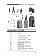
Page 13: ...PARTS SCHEMATIC 13 PARTS SCHEMATIC T3 TOOL SYSTEM SCHEMATIC MOTOR ASSEMBLY...

Page 14: ...Motor Sleeve Motor Mount Retaining Ring and Fan Blade 10 401356 MOTOR SLEEVE 11 900470 MOTOR MOUNT 12 401355 MOTOR RETAINING RING 13 404601 HEAD SWITCH 14 B0078 CYLINDER HEAD 15 403992 O RING CYLINDE...

Page 15: ...D 7 B0006A TRIGGER ASSEMBLY 8 B0050A FUEL CONNECTION ASSEMBLY 9 B0160 FUEL VALVE ASSEMBLY 10 B0100A HANDLE SCREWS 11 B0176 LEFT RIGHT HANDLE ASSEMBLY 12 B0144 REAR FOOT ASSEMBLY T3SS ONLY 13 B0018 SPA...

Page 16: ...407100277 OCT 07 6 E150100 WORK CONTACT ELEMENT WCE M150200 MAGNETIC WORK CONTACT ELEMENT 8 B0047A GUIDE BLOCK ASSEMBLY B0171 SPACER STAND OFF NUT 9 B0179 SHROUD PLUG 10 B0218 WCE RETENTION KIT TOOLS...

Page 17: ...SHEAR BLOCK KIT T3MAG Shear Block T Nuts 2 Screws 2 7 B0111A PIN GUIDE ASSEMBLY W SET SCREW 8 B0122A ACTUATOR ASSEMBLY 8A B0128 SCREW ACTUATOR TO CAGE 9 B0031A PISTON ASSEMBLY W PISTON RINGS 10 B0068...

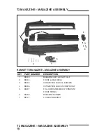
Page 18: ...AGAZINE ASSEMBLY KEY PART NUMBER DESCRIPTION 1 B0203 MAGAZINE LEFT RIGHT HALF 2 B0204 FRONT REAR RAILS 3 B0205 CONNECTION BLOCK SCREWS 4 B0206 CONNECTION BLOCK SCREWS ONLY 5 B0207 FOLLOWER ASSEMBLY W...

Page 19: ...run Battery in off position Fully insert Battery tool LED is off Battery Cell is Charge Battery Cell according to not charged Operating Manual Battery terminals or Clean Battery Cell terminals battery...

Page 20: ...ol Sleeve or Clean tool per Cleaning Procedure O Rings are dirty Returning Purging Stage of Operation Tool operated and Built up dirt and Clean Piston and Nose bore with drove fastener but debris on P...

Page 21: ...eplaces This warranty does not apply to part replacement required due to normal wear This warranty is void as to any tool which has been subjected to misuse abuse accidental or intentional damage use...

Page 22: ...CENTER VISIT OUR WEB SITE AT WWW RAMSET COM OR CALL 800 241 5640 Concrete Fastening Systems Glendale Heights IL 60139 800 RAMSET6 1 800 726 7386 www ramset com Buy with Confidence Buy From Your Autho...

Reviews: