ICI16• 14
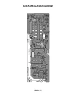
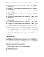
38. Install R14, 100 ohm resistor [brown-black-brown], above C13. Install
vertically.
39. Install R15, 100 ohm resistor [brown-black-brown], to the left of R14.
Install vertically.
40. Install R17, 100 ohm resistor [brown-black-brown], to the left of R15.
Install vertically.
41. Install R16, 100 ohm resistor [brown-black-brown], to the left of R17.
Install vertically.
42. Install R18, 100 ohm resistor [brown-black-brown], to the left of R17.
Install vertically.
43. Install R19, 10 K ohm resistor [brown-black-orange], to the left of R18.
Install vertically.
44. Install R9, 10 K ohm resistor [brown-black-orange], to the left of R19.
Install vertically.
45. Install R10, 10 K ohm resistor [brown-black-orange], to the left of R9.
46. Install R11, 10 K ohm resistor [brown-black-orange], to the left of R10.
47. Install S2, dip switch block. The switches should face the outside of
the PC board to make it easier to flip them later.
48. We have one last part to install and it’s going on the back side of the
board with the first connectors we installed. It is the IR sensor module, U3.
It goes into the three holes next to C14. Check its position on the topside
of the board, then install it on the bottom. Leave the leads standing up off
the board a bit to make it easier for your remote to “see” the sensor and
solder it so that it’s facing the outside edge of the PC board. Solder all
three leads.
CONGRATULATIONS !
Your Remote Control Interface kit is now complete! Have a final look over your
work, paying particular attention to the orientation of diodes, capacitors, and
IC’s. Remember that any problems you find now can save time and effort after
the unit has been cased up and final assembled.
TESTING AND PROGRAMMING YOUR ICI16
To begin testing the ICI16 we will need the following items:
Regulated 5VDC power.
An infrared remote control


