UAM4
•
14
39. Install 3 pin header H7, located along the right edge of the board.
40. Install 3 pin header H8, located along the right edge of the board.
41. Install 3 pin header H9, located along the right edge of the board.
42. Install 3 pin header H1, located on the lower left edge of the board.
43. Install 3 pin header H2, located on the lower left edge of the board.
44. Install 2 pin header H3. This is located near the lower center edge of
the board.
45. Install the 2.1mm power jack J5 located on the left middle edge of the
board.
46. Locate the provided heavy insulated 24awg stranded jumper wire and
install it on the bottom of the board between JP1, located near the power
connector, J5, side near C12 and C13, and JP2 located near the upper
right of U1 between C16 and C14.
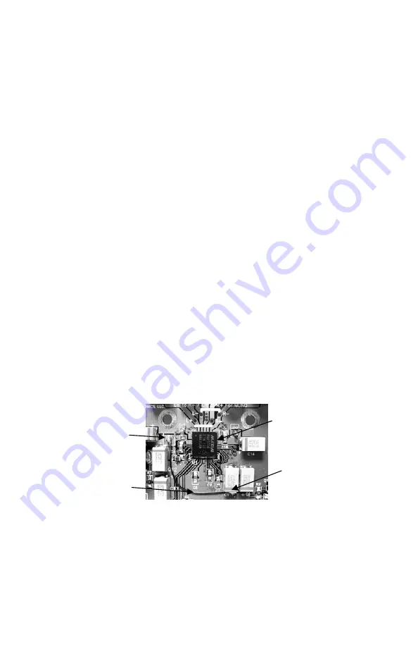
47. Locate the light weight 24awg solid insulated jumper wire. This wire
has an enamel type insulation. By applying a bead of solder on your iron
and then holding the tip of the wire tight against the soldering iron in the
solder bead this insulation will ’melt’ after a few seconds and the solder
will coat the copper wire. Cut the wire to the length required, prepare the
ends as described and then install it on the top side of the board between
JP1, located near the power connector J5, C12, C13, and the “+” side of
C5 by first soldering one end to JP1. Now solder the other end to the ‘+’
side of capacitor C5, located off the lower right corner of U1, by carefully
flowing a little extra solder on the “+” side of C5 and then solder the wire
to this point. Lay the wire against the board so it is routed somewhat
away from the components along it’s path. See the picture below for more
detail.
Once again check over all of your work. Check that all components are
placed properly and there are no solder bridges between components and
traces.
That’s all folks!!! (For the assembly that is…)
JP1
C5+
JUMPER
U1
Summary of Contents for UAM4
Page 18: ...UAM4 18 UAM4 SCHEMATIC DIAGRAM...
Page 19: ...UAM4 19...


