WEB1
•
9
Cut three pieces of wire that will be the runners that the WEB1 slides on.
The two side runners are 2 1/4” long. The back runner is 1 3/4” long. The
side runners need to be bent into a “U” shape with the front part about 1/2”
long and the back part should be about 1/4” long. These act kind of like a
sled that the WEB1 slides across the floor on. The back runner is sort of
like a big foot that pushes the WEB1 from behind. It should be bent into a
square shape and soldered into the holes as shown in the picture.
18. Now you need to install the little motors on the circuit board. The mo-
tors come with a silicone thingy on them. This will help keep the motor in
place when it is running.
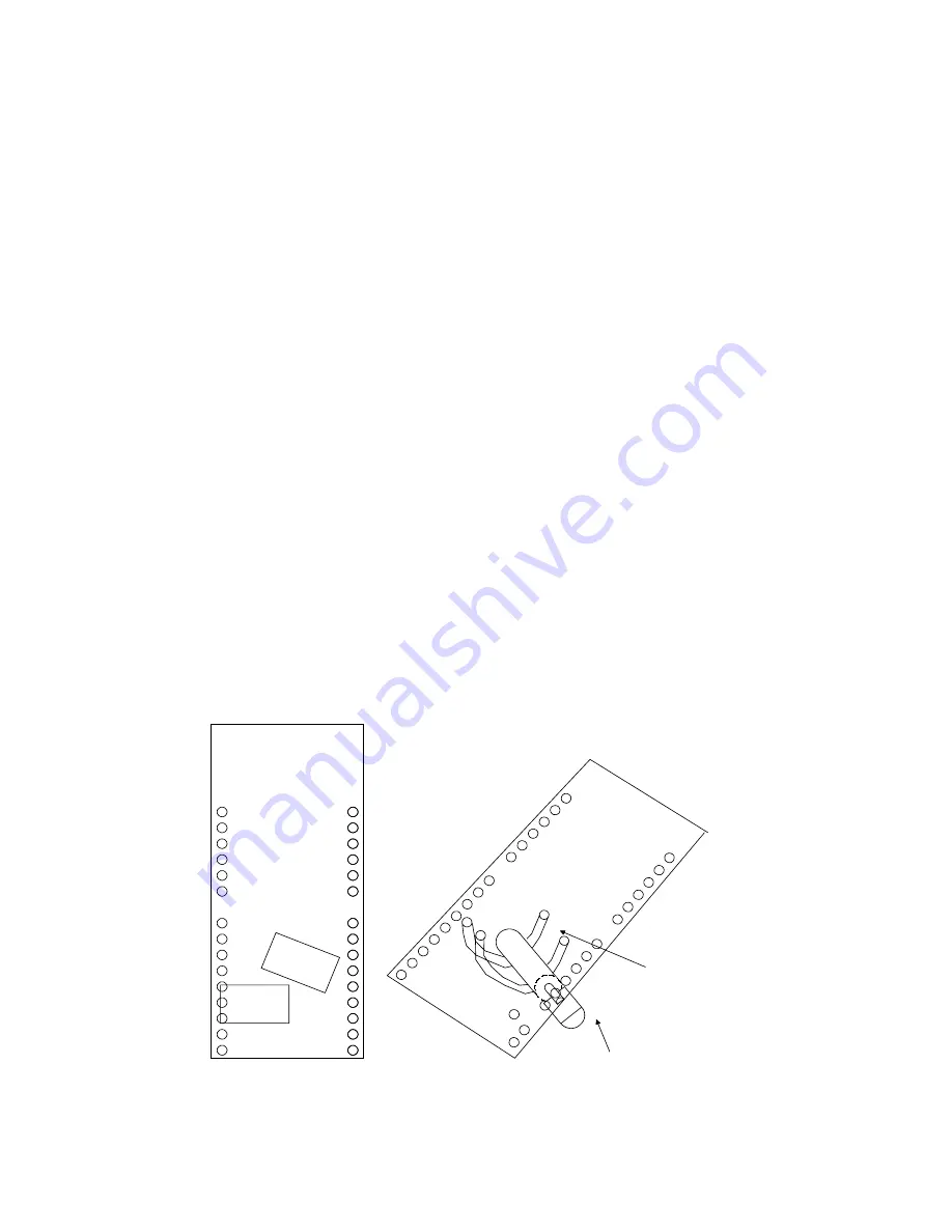
19. Now you need to determine where you’re attaching the motors to the
PC board. To do this, take one of the motors and hold it under the BOT-
TOM of the board so that it roughly lines up with the rectangular outline on
the TOP of the board. This is just to help you place the motor in the right
spot. Take a look at the picture below or the parts layout diagram and note
that one pattern is at an angle while one is straight. The one at an angle is
for steering the bug when it approaches an obstacle, the straight one pro-
pels your electronic friend forward. It isn’t critical that the steering motor
be angled, but this may improve the steering performance. There are
many holes on the board for you to solder the hold-down wire into. Just
pick ones that are conveniently close to the motor so that the wire has a
snug hold on it. Now, cut 2, 3/4” pieces of tinned wire and place one end
of each piece in a hole that you intend to use to mount the motor. Solder
this end in place on each of the wires. Now wrap each piece of wire one
by one around the motor making sure that the pads on the motor are fac-
ing out where you can solder the wires to them and run each wire back up
through the board. Solder each wire on the top of the circuit board so that
Top of Board
Motor Under Board
Wire
Summary of Contents for Walking Electronic Bug WEB1
Page 10: ...WEB1 10 WEB1 BOARD PARTS LAYOUT DIAGRAM...
Page 11: ...WEB1 11...


