background image

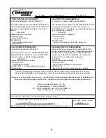
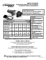
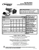
GUIDE DE L'UTILISATEUR

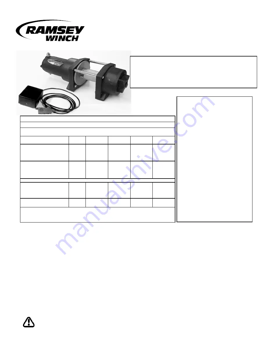
Treuil électrique modèle ATV 8 avec commutateur

de commande à distance à bouton-poussoir

MISE EN GARDE : S'ASSURER DE LIRE ET DE COMPRENDRE CE MANUEL AVANT D'INSTALLER ET D'UTILISER LE
TREUIL. PRENDRE CONNAISSANCE DES CONSIGNES DE SÉCURITÉ.

Utilisation prévue : autodépannage de véhicules et traction de charges.

RAMSEY


WINCH COMPANY

Post Office Box 581510 Tulsa, Oklahoma 74158-1510 USA


Phone: (918) 438-2760 Fax: (918) 438-6688

Visit us at http://ww.ramsey.com

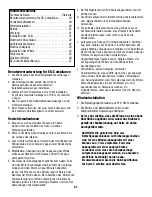
English (Original Instructions) . . . . . . . . . . . . . . .     1
Français (Traduction des instructions originales) . .  10
Deutsch (Übersetzung der Originalanleitung) . . . . .  18
Español (Traducción de las instrucciones originales) 28

OM-914220-1012-B

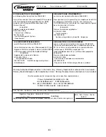
Traction du câble, première couche

8 kN (816,47 kg)

Niveau sonore

81 dB

Plage de température ambiante

-28 à 60 °C

COUCHE DE CÂBLE

1

2

3

4

Traction nominale par
couche de câble

kN

8

6,6

5,3

4,8

lb

1,800

1,400

1,200

1,100

Capacité cumulative de
câble par couche

m

1,5

4,5

6

10,6

ft

5

15

20

37

Traction du câble,
première couche

kN

À 

2,6

5,3

6,6

lb

vide

600

1,200

1800

Intensité du moteur

12V

31

72

101

135

* Ces caractéristiques sont basées sur l'utilisation du câble métallique recommandé de 5
mm de calibre 1960

AVERTISSEMENTS :
L'UTILISATEUR DOIT VEILLER À CE QUE TOUT
OPÉRATEUR REÇOIVE LA FORMATION
NÉCESSAIRE.
L'OPÉRATEUR DOIT TOUJOURS TRAVAILLER
EN CONFORMITÉ AVEC LES INSTRUCTIONS
D'UTILISATION.
L'EMBRAYAGE DOIT ÊTRE COMPLÈTEMENT
ENCLENCHÉ AVANT DE DÉMARRER LE
TREUIL.
NE JAMAIS RELÂCHER L'EMBRAYAGE EN
PRÉSENCE D'UNE CHARGE.
NE JAMAIS SE PLACER SOUS UNE CHARGE
SOULEVÉE NI À PROXIMITÉ.
RESTER À L'ÉCART DU CÂBLE LORS DU
TREUILLAGE. NE PAS ESSAYER DE GUIDER LE
CÂBLE.
NE PAS UTILISER LE TREUIL POUR
SOULEVER, MAINTENIR OU TRANSPORTER
DES PERSONNES.
IL CONVIENT DE CONSERVER AU MINIMUM
DEUX TOURS DE CÂBLE AUTOUR DU
TAMBOUR POUR MAINTENIR LA CHARGE.
ÉVITER TOUTE SITUATION DE DÉPLACEMENT
DE LA CHARGE OU D'À-COUPS. ÉVITER LES
MOUVEMENTS SACCADÉS.

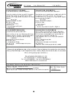
Ramsey Représentant autorisé dans la comuauté 

:

(Veuillez prendre contact uniquement pour des questions réglementaires.)

ProLux Systemtechnik GmbH & Co. KG

Am Schinderwasen 7 · D-89134 Blaustein

Tel.: +49 (0)7304/9695-0 · Fax: +49 (0)7304/9695-40

E-Mail: info@prolux.de · www.prolux.de

Summary of Contents for ATV 8

Page 1: ...NCHING SHALL BE AVOIDED English Original Instructions 1 Français Traduction des instructions originales 10 Deutsch Übersetzung der Originalanleitung 18 Español Traducción de las instrucciones originales 28 OM 914220 1012 B First Layer Line Pull 8kN 1800 lb Noise Level 81 db Ambient Temperature Range 28 to 60 C 20F to 140F LAYER OF ROPE 1 2 3 4 Rated Line Pull Per Layer kN 8 6 6 5 3 4 8 lb 1 800 1 ...

Page 2: ...ebene Winden ISO 9001 2000 Qualitätsmanagementsysteme Anforderungen DECLARACIÓN EC DE CONFORMIDAD según se define en la directiva de máquinas 2006 42 EC Con la presente declaramos que el modelo de cabestrante ATV 8 se halla en conformidad con la siguiente directiva siempre que el USUARIO cumpla todas las responsabili dades descritas en el Manual del propietario 2006 42 EC Normas armonizadas aplica...

Page 3: ... not allow the rope to slip through your hand and do not approach the winch too closely I Observe spooling of rope onto drum Side pulls can cause rope to pileup at one end of the drum To correct uneven stacking spool out that section of the rope and move it to the other end of the drum and continue winching Uneven spooling which causes rope pileup can interfere with the winch tie rods causing dama...

Page 4: ...lubricated with broad temperature range lithium based grease Lubricate rope periodically using light penetrating oil Inspect for broken strands and replace if necessary If the rope becomes worn or damaged it must be replaced Rope Installation Note Rope must be installed so that it feeds from the bottom of the drum Unwind the new rope by rolling it out along the ground to prevent kinking Remove old...

Page 5: ...ole of the motor 4 Connect the black with yellow stripe motor lead to the 1 pole of the motor 5 The remote switch plugs into the receptacle on the solenoid The remote control switch is waterproof It has push but ton stations on either side It is designed this way to pre vent quick winch reversals which can lead to solenoid failure Make sure the motor has stopped fully before reversing To actuate w...

Page 6: ...D WIRE SPLICE GROUND TO VEHICLE IGNITION FUSE SWITCH BATTERY Rocker switch in OFF position E STOP SWITCH BLACK MOTOR LEAD E STOP SOLENOID RED 13 RED LEAD BLACK GROUND YELLOW FROM E STOP SWITCH BLACK BATTERY LEAD BLACK W YELLOW STRIPE MOTOR LEAD YELLOW FROM E STOP SWITCH CAPACITOR ...

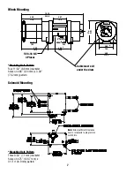
Page 7: ...UM CABLE SPOOLS IN UNDER DRUM 4 40 111 8 13 19 335 0 2 97 75 4 Ø1 75 44 4 Mounting Hole Pattern Four 11 32 8 6 mm diameter holes on 4 88 124 mm x 3 00 76 2 mm pattern 5 16 18 NC 4 Places 7 Mounting Hole Pattern Three 9 32 7 1 mm diameter holes on 4 75 120 7 mm x 4 13 104 9 mm pattern Note Allow sufficient clearance next to receptacle to plug remote switch into Cable must exit under the drum ...

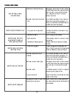
Page 8: ...osion clean and grease Replace with larger capacity charging system MOTOR RUNS BUT DRUM DOES NOT TURN Clutch not engaged if clutch engaged but symptoms still exist it will be necessary to disassemble winch to determine cause and repair MOTOR WILL NOT OPERATE Defective solenoid or stuck solenoid Defective remote switch plug Defective motor Loose connections Jar solenoid assembly to free contacts Ch...

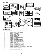
Page 9: ...MOUNTING KIT 11 1 256116 BRAKE KIT 12 1 289197 72 BLACK BATTERY LEAD 13 1 289199 72 RED BATTERY LEAD 14 1 289203 48 BLACK MOTOR LEAD 15 1 289204 48 BLACK W YELLOW STRIPE MOTOR LEAD 16 1 422023 HAWSE FAIRLEAD 17 1 282067 E STOP SWITCH KIT NOT SHOWN 18 1 434574 NAME AND DATA TAG 19 1 434577 WARNING TAG 18 INTENDED PURPOSE VEHICLE RECOVERY AND PULLING OF LOADS READ OPERATING INSTRUCTIONS BEFORE USE F...

Page 10: ...e couche kN À 2 6 5 3 6 6 lb vide 600 1 200 1800 Intensité du moteur 12V 31 72 101 135 Ces caractéristiques sont basées sur l utilisation du câble métallique recommandé de 5 mm de calibre 1960 AVERTISSEMENTS L UTILISATEUR DOIT VEILLER À CE QUE TOUT OPÉRATEUR REÇOIVE LA FORMATION NÉCESSAIRE L OPÉRATEUR DOIT TOUJOURS TRAVAILLER EN CONFORMITÉ AVEC LES INSTRUCTIONS D UTILISATION L EMBRAYAGE DOIT ÊTRE ...

Page 11: ...folgt 2006 42 EC Angewandte harmonisierte Normen EN 14492 1 2006 Kraftgetriebene Winden ISO 9001 2000 Qualitätsmanagementsysteme Anforderungen DECLARACIÓN EC DE CONFORMIDAD según se define en la directiva de máquinas 2006 42 EC Con la presente declaramos que el modelo de cabestrante ATV 8 se halla en conformidad con la siguiente directiva siempre que el USUARIO cumpla todas las responsabilidades d...

Page 12: ...sser glisser sur la main ne pas s approcher trop près du treuil I Examiner l enroulement du câble sur le tambour Les tensions latérales peuvent causer l empilement du câble sur un côté du tambour Pour corriger cette anomalie dérouler la section empilée et la déplacer vers l autre côté du tambour puis continuer le treuillage Un enroulement irrégulier provoquant un empilement du câble peut nuire à l...

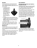
Page 13: ...e comme protection anticorrosion Toutes les pièces mobiles du treuil ont été lubrifiées de façon permanente avec de la graisse au lithium plage de températures étendue Le câble doit être lubrifié régulièrement avec de l huile légère pénétrante Inspecter le câble et le remplacer s il est éraillé Un câble usé ou endommagé doit être immédiatement remplacé Installation du câble Remarque installer le c...

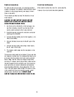
Page 14: ...oteur strié de jaune sur la borne n 1 du moteur 6 La télécommande est branchée sur la prise du solénoïde La télécommande est étanche Elle comporte un dispositif de commande de chaque côté Ces dispositifs sont destinés à éviter les inversions rapides de sens de fonctionnement du treuil pouvant causer une défaillance du solénoïde S assurer que le moteur du treuil est entièrement arrêté avant toute i...

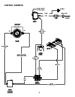
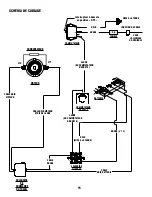
Page 15: ...S L ALLUMAGE DU VÉHICULE FUSIBLE COMMUTATEUR BATTERIE Interrupteur à bascule en position OFF COMMUTATEUR D ARRÊT E CÂBLE NOIR MOTEUR SOLÉNOÏDE D ARRÊT E ROUGE n 13 CÂBLE ROUGE NOIR MISE À LA TERRE JAUNE DU COMMUTATEUR D ARRÊT E CÂBLE NOIR BATTERIE CÂBLE NOIR MOTEUR STRIÉ DE JAUNE JAUNE DU COMMUTATEUR D ARRÊT E CONDENSATEUR ...

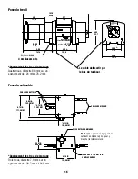
Page 16: ...age Quatre trous diamètre 8 6 mm sur un agencement de 124 mm x 76 2 mm 5 16 18 NC 4 emplacements 16 CÂBLES DE BATTERIE CÂBLES DE MOTEUR PRISE DE TÉLÉCOMMANDE 6 00 IN 153 9 MM 6 75 IN 3 EMPLACEMENTS 171 5 MM 4 75 IN 120 7 MM 4 13 IN 104 6 MM 3 50 IN 88 9 MM 5 19 IN 131 8 MM 1 4 20 UNC X 13 5 MM LONG Agencement des trous de montage Trois trous diamètre 7 1 mm sur un agencement de 120 7 mm x 104 9 mm...

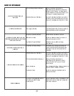
Page 17: ...t nettoyer ou graisser au besoin Remplacer par un système de charge plus puissant LE MOTEUR TOURNE MAIS PAS LE TAMBOUR Le tambour n est pas embrayé Si le tambour est embrayé mais refuse de tourner le treuil doit alors être démonté pour déterminer la cause de l anomalie et faire la réparation LE MOTEUR REFUSE DE TOURNER Solénoïde bloqué ou défectueux Prise de télécommande défectueuse Moteur défectu...

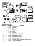
Page 18: ...REIN 12 1 289197 CÂBLE NOIR BATTERIE 1 8 M 13 1 289199 CÂBLE ROUGE BATTERIE 1 8 M 14 1 289203 CÂBLE NOIR MOTEUR 1 2 M 15 1 289204 CÂBLE NOIR MOTEUR STRIÉ DE JAUNE 1 2 M 16 1 422023 GUIDE CÂBLE À ÉCUBIER 17 1 282067 COFFRET DU COMMUTATEUR D ARRÊT E NON ILLUSTRÉ 18 1 434574 ÉTIQUETTE SIGNALÉTIQUE 19 1 434577 ÉTIQUETTE D AVERTISSEMENT 18 INTENDED PURPOSE VEHICLE RECOVERY AND PULLING OF LOADS READ OPE...

Page 19: ...DASS DAS BEDIENPERSONAL DIE ERFORDERLICHE SCHULUNG ERHÄLT DER BEDIENER MUSS BEIM BETRIEB STETS DIE BEDIENUNGSANWEISUNGEN BEFOLGEN VOR BEGINN DES WINDENBETRIEBS MUSS SICHERGESTELLT WERDEN DASS DIE KUPPLUNG VOLLSTÄNDIG EINGERÜCKT IST DIE KUPPLUNG NICHT UNTER LAST AUSRÜCKEN NIEMALS UNTER ODER NEBEN ANGEHOBENEN LASTEN STEHEN WÄHREND DES ZIEHENS EINEN SICHEREN ABSTAND ZUM SEIL EINHALTEN NICHT VERSUCHEN...

Page 20: ...ndbuch befolgt 2006 42 EC Angewandte harmonisierte Normen EN 14492 1 2006 Kraftgetriebene Winden ISO 9001 2000 Qualitätsmanagementsysteme Anforderungen DECLARACIÓN EC DE CONFORMIDAD según se define en la directiva de máquinas 2006 42 EC Con la presente declaramos que el modelo de cabestrante ATV 8 se halla en conformidad con la siguiente directiva siempre que el USUARIO cumpla todas las responsabi...

Page 21: ...tseil nicht durch die Hand gleiten lassen und nicht zu nahe an die Winde treten I Aufspulen des Seils auf Trommel beobachten Seitlicher Zug kann Seilstau am Ende der Trommel bewirken Um ungleichmäßige Stapelung zu korrigieren den betroffenen Abschnitt des Seils abspulen und auf die andere Seite der Trommel verlegen und dann weiterwinden Ungleichmäßiges Spulen kann zu Seilstau führen der die Zugsta...

Page 22: ...eratur tolerantem lithiumbasiertem Schmiermittel ständig geschmiert Das Drahtseil regelmäßig mit einem leichten Penetrieröl schmieren Auf gebrochene Litzen überprüfen und nötigenfalls ersetzen Ein abgenutztes oder beschädigtes Drahtseil muss ersetzt werden Installation des Seils Anmerkung Das Drahtseil muss so installiert werden dass es an der Unterseite der Trommel beginnt Zum Abwickeln das neue ...

Page 23: ...t dem gelben Streifen mit dem Pol Nr 1 des Motors verbinden 6 Der Fernbedienungsschalter wird am Anschluss am Magnetschalter eingesteckt Der Fernbedienungsschalter ist wasserdicht Er ist an beiden Seiten mit Drucktasten versehen Dadurch soll ein schnelles Wechseln der Wickelrichtung der Winde was zu einem Ausfall des Magnetschalters führen kann verhindert werden Darauf achten dass der Motor vollst...

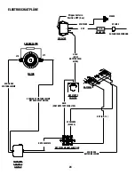
Page 24: ...ZEUGZÜNDUNG SICHERUNG SCHALTER BATTERIE Wippschalter in Position OFF Aus NOTSTOPPS CHALTER SCHWARZE MOTORKLEMME NOTSTOPPMAGNETSCHALTER ROT NR 13 ROTE KLEMME SCHWARZE MASSE GELB VOM NOTSTOPPSCH ALTER SCHWARZE BATTERIEKLEMME SCHWARZE MOTORKLEMME MIT GELBEM STREIFEN GELB VOM NOTSTOPPSCHALTER KONDENSATOR ...

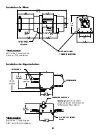
Page 25: ...75 4 Ø1 75 44 4 Bohrlochmuster Vier Löcher 8 6 mm Durchm 124 mm x 76 2 mm Muster 5 16 18 NC 4 Stellen 25 BATTERIEKABEL MOTORKLEMMEN FERNBEDIENUNGSANSCHLUSS 6 00 IN 153 9 MM 6 75 IN 3 Stellen 171 5 MM 4 75 IN 120 7 MM 4 13 IN 104 6 MM 3 50 IN 88 9 MM 5 19 IN 131 8 MM 1 4 20 UNC X 13 5 MM LANG Bohrlochmuster Drei Löcher 7 1 mm Durchm 120 7 mm x 104 9 mm Muster Anmerkung Neben dem Anschluss ausreiche...

Page 26: ...nd schmieren Stärkere Lichtmaschine einbauen MOTOR DREHT SICH ABER TROMMEL DREHT SICH NICHT Kupplung nicht eingerückt Wenn die Symptome nach dem Einrücken weiter bestehen muss die Winde auseinander gebaut die Ursache gefunden und behoben werden MOTOR FUNKTIONIERT NICHT Magnetschalter ist defekt oder klemmt Defekter Fernbedienungs schalter Anschluss Defekter Motor Lose Anschlüsse Magnetschalter Bau...

Page 27: ...51248 MAGNETSCHALTER ANBAUSATZ 11 1 256116 BREMS SATZ 12 1 289197 SCHWARZE BATTERIEKLEMME 1 8 m 13 1 289199 ROTE BATTERIEKLEMME 1 8 m 14 1 289203 SCHWARZE MOTORKLEMME 1 2 m 15 1 289204 SCHWARZE MOTORKLEMME MIT GELBEM STREIFEN 1 2 m 16 1 422023 SEILMAUL 17 1 282067 NOTSTOPPSCHALTER SATZ NICHT ABGEBILDET 18 1 434574 TYPEN UND DATENSCHILD 19 1 434577 WARNSCHILD 18 INTENDED PURPOSE VEHICLE RECOVERY AN...

Page 28: ...6 5 3 6 6 lb carga 600 1 200 1800 Consumo en amperaje 12V 31 72 101 135 Estas especificaciones se basan en un cable metálico recomendado de 5 mm de clase 1960 ADVERTENCIAS EL USUARIO DEBERÁ GARANTIZAR QUE EL PERSONAL QUE USE EL EQUIPO HAYA RECIBIDO LA FORMACIÓN NECESARIA EL OPERADOR DEBERÁ TRABAJAR SIEMPRE SIGUIENDO LAS INSTRUCCIONES DE FUNCIONAMIENTO EL EMBRAGUE DEBE ESTAR TOTALMENTE ENGRANADO AN...

Page 29: ... befolgt 2006 42 EC Angewandte harmonisierte Normen EN 14492 1 2006 Kraftgetriebene Winden ISO 9001 2000 Qualitätsmanagementsysteme Anforderungen DECLARACIÓN EC DE CONFORMIDAD según se define en la directiva de máquinas 2006 42 EC Con la presente declaramos que el modelo de cabestrante ATV 8 se halla en conformidad con la siguiente directiva siempre que el USUARIO cumpla todas las responsabilidade...

Page 30: ...demasiado al cabestrante I Observe el proceso de enrollado del cable sobre el tambor Las fuerzas de tiro laterales pueden hacer que el cable se acumule en un extremo del tambor Para corregir la falta de uniformidad en el enrollado desenrolle la sección del cable no uniforme pásela al otro extremo del tambor y continúe con el proceso de enrollado El enrollado no uniforme causante de las acumulacion...

Page 31: ...estrante están permanentemente lubricadas con una grasa de litio resistente a un amplio rango de temperaturas Lubricar el cable periódicamente con un aceite ligero y penetrante Comprobar que el cable no tenga hilos sueltos y reemplazarlo si es necesario Si el cable se desgasta o daña debe ser reemplazado Instalación del cable metálico Nota el cable se debe instalar de forma que salga por la parte ...

Page 32: ... Conecte el cable negro con raya amarilla del motor al borne número 1 del motor 6 El teleinterruptor se enchufa en el receptáculo del solenoide El teleinterruptor es impermeable Dispone de teclados de botones a cada lado y está diseñado de esta forma para evitar las inversiones repentinas del cabestrante lo que podría provocar un fallo del solenoide Asegúrese de que el motor se haya detenido total...

Page 33: ...ÍA Conmutador basculante en la posición de apagado OFF INTERRUPTOR DE PARADA DE EMERGENCIA CABLE NEGRO DEL MOTOR SOLENOIDE DE PARADA DE EMERGENCIA ROJO Núm 13 CABLE ROJO NEGRO PUESTA A TIERRA AMARILLO DESDE EL INTERRUPTOR DE PARADA DE EMERGENCIA CABLE NEGRO DE LA BATERÍA CABLE NEGRO CON RAYA AMARILLA DEL MOTOR AMARILLO DESDE EL INTERRUPTOR DE PARADA DE EMERGENCIA CONDENSADOR ...

Page 34: ...os de 8 6 mm de diámetro en una configuración de 124 mm x 76 2 mm 5 16 18 NC 4 lugares 34 CABLES DE LA BATERÍA CABLES DEL MOTOR RECEPTÁCULO DEL CONTROL REMOTO 6 00 IN 153 9 MM 6 75 IN 3 LUGARES 171 5 MM 4 75 IN 120 7 MM 4 13 IN 104 6 MM 3 50 IN 88 9 MM 5 19 IN 131 8 MM 1 4 20 UNC X 13 5 MM DE LARGO Configuración de los orificios de montaje Tres orificios de 7 1 mm de diámetro en una configuración ...

Page 35: ...í como que está limpio y engrasado Cambie a un sistema de carga de mayor capacidad EL MOTOR FUNCIONA PERO EL TAMBOR NO GIRA El embrague no está engranado Si el embrague se engrana pero el síntoma persiste habrá que desmontar el cabestrante para determinar la causa y repararlo EL MOTOR NO FUNCIONA Solenoide defectuoso o atascado Enchufe del teleinterruptor defectuoso Motor defectuoso Conexiones sue...

Page 36: ...OTOR 10 1 251248 KIT DE MONTAJE DEL SOLENOIDE 11 1 256116 KIT DEL FRENO 12 1 289197 CABLE NEGRO DE LA BATERÍA DE 1 8 M 13 1 289199 CABLE ROJO DE LA BATERÍA DE 1 8 M 14 1 289203 CABLE NEGRO DEL MOTOR DE 1 2 M 15 1 289204 CABLE NEGRO CON RAYA AMARILLA DEL MOTOR DE 1 2 M 16 1 422023 GUÍACABOS DE ESCOBÉN 17 1 282067 KIT DEL INTERRUPTOR DE PARADA DE EMERGENCIA NO MOSTRADO 18 1 434574 PLACA DE NOMBRE Y ...

Reviews: