background image

Installation Details

Winch Mounting

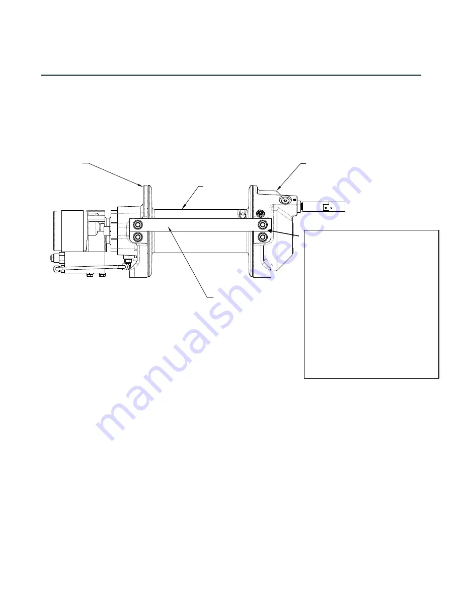
ESSENTIAL MOUNTING INSTRUCTIONS TO MAINTAIN ALIGNMENT OF PLANETARY WINCH 

COMPONENTS:

It is most important that this winch be mounted securely so that the three major sections (the 

motor end, the cable drum, and the gear housing end) are properly aligned. Excessive bushing 

wear and difficulty in free-spooling are usually symptoms of misalignment.

If the winch is foot mounted, then at least one tie-plate must remain mounted at midpoint of 

winch to maintain alignment. It is always preferred to use BOTH tie-plates in the final installed 

configuration.

When mounting the winch with other than the recommended Ramsey Angle Kit, the mounting 

hole patterns described in the Dimensional drawings of this manual should be used. The 

mounting surface must be flat within .015 inch and sufficiently stiff to resist flexing. If a steel 

plate is used for foot mounting, it should be .750 inch thick. For this mounting application eight 

(8) 1/2-13NC x 1-1/2” long grade 5 cap screws with lock washers will be needed to mount winch. 

Cap screws should be tightened to 55 ft-lb (75 Nm) torque.

NOTE: If angles or a steel plate are used in mounting winch, tie-plates provided with winch are 

to be attached to the remaining mounting pads, whether they be side or foot.

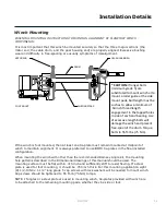
* CAUTION: 

If longer bolts 

(minimum grade 5) are 

substituted to mount winch or to 

mount a roller guide at the side 

mount pads, bolt length must be 

such as to allow a minimum of 

.50 inch thread length 

engagement in the tapped holes 

in side of each end bearing. Use 

of excessive length bolts will 

damage the winch and prevent 

free-spool of the drum. Torque 

bolts to 55 ft-lbs. (75 Nm).

914307

11

GEAR HOUSING EN

DRUM

MOTOR END

FOOT MOUNT

SHIPPING STRAP

Summary of Contents for HD-P 4000

Page 1: ...123966 PLANETARY WINCH Mailing Address P O Box 58151 Tulsa OK 74158 Phone 918 438 2760 Fax 918 438 6688 www ramseyindustries com READ AND UNDERSTAND THIS MANUAL BEFORE INSTALLATION AND OPERATION OF W...

Page 2: ...its use there are dangers if improperly used Please read this manual carefully It contains useful ideas in obtaining the most e cient operation from your Ramsey Winch and safety procedures you need to...

Page 3: ...itle Page Introduction 5 Winch Specifications 7 Installation Details 11 Winch Operation 13 Maintenance 15 Troubleshooting Guide 17 Parts Identification 19 Limited Warranty backcover 914307 3 Table of...

Page 4: ...THIS PAGE IS INTENTIONALLY LEFT BLANK...

Page 5: ...tion or deviation to the winchshould onlybe made by RamseyWinchCompany Do not try to guide the cableduring a loaded pull Keep yourselfand others a safedistance to the side when pulling aload Do not st...

Page 6: ...THIS PAGE IS INTENTIONALLY LEFT BLANK...

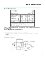
Page 7: ...VE REQUIRED 2500 PSI RELIEF VALVE SETTING 15 GPM FLOW RATE MAX MOTOR AND WINCH MAY BE DAMAGED IF MAX FLOW RATE IS EXCEEDED 10 MICRON NOMINAL FILTRATION Typical Layout shown below NOTE The rated line p...

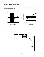
Page 8: ...Performance Charts 914307 8 11 75 9 25 90 5 02 2 72 0 50 General Dimensions Handle 276070 0 2000 4000 6000 0 500 1000 1500 2000 2500 3000 Line Pull Lbs Pressure PSI 0 20 40 60 80 100 120 5 10 15 Line...

Page 9: ...5 8 27 210 1 FLANGE 7 49 164 8 1 25 31 7 8 38 213 1 4 25 107 9 2 21 56 1 2 21 56 1 4 19 106 4 8 38 212 7 9 96 252 9 5 01 127 3 11 34 288 0 5 67 144 0 5 28 125 2 5 51 139 9 4 33 109 9 2 16 55 1 TYP 1 1...

Page 10: ...THIS PAGE IS INTENTIONALLY LEFT BLANK...

Page 11: ...e mounting surface must be flat within 015 inch and sufficiently stiff to resist flexing If a steel plate is used for foot mounting it should be 750 inch thick For this mounting application eight 8 1...

Page 12: ...k with plastic or similar tape to prevent fraying 2 Place taped end of cable into hole in cable drum as shown below Use the 3 8 16NC x 1 2 long hex socket drive setscrew to secure cable to drum 3 Care...

Page 13: ...ind for a neat lay of the cable When pulling a heavy load place a blanket jacket and tarpaulin over the cable about five or six feet behind the hook In the event of a broken cable this will slow the s...

Page 14: ...THIS PAGE IS INTENTIONALLY LEFT BLANK...

Page 15: ...ch is fully engaging See OPERATION instructions above for the appropriate clutch shifter FOR MANUAL CLUTCH ONLY Monthly disengage clutch put several drops of oil on the clutch handle shaft and work cl...

Page 16: ...THIS PAGE IS INTENTIONALLY LEFT BLANK...

Page 17: ...ear Check bolt length Bolt thread MUST NOT engage threaded holes in sides of end bearing more than the 50 inch thread depth in the end bearing BRAKE WILL NOT HOLD Incorrect directional control valve c...

Page 18: ...THIS PAGE IS INTENTIONALLY LEFT BLANK...

Page 19: ...Parts Identification 914307 19 Winch 123966 3 4 2 15 22 45 44 19 23 29 37 26 24 41 43 7 33 31 35 30 8 32 34 5 6 36 14 25 11 18 17 21 20 38 46 12 18 39 27 9 40 47 10 13 1 42 23 23 28 16...

Page 20: ...8 337 11 1 364178 STRAP SHIPPING 35 1 462072 RING BACKUP 2 268 ID X 076 THK 8 331 12 1 395521 TIE PLATE 36 1 462073 O RING 3 234 ID X 139 THK 2 236 13 1 412196 BUSHING DRUM GEAR END 37 1 470033 SPIROL...

Page 21: ...ts Identification 914307 21 Handle 276070 Item No Quantity Part No Description 1 1 358078 SHIFTER HANDLE 2 2 418563 WASHER FLAT 1 2 GRADE 8 3 2 490082 RETAINER CLIP 4 1 494176 SPRING COMPRESSION 1 2 4...

Page 22: ...rations have been made unless authorized by Manufacturer or for equipment misused neglected or which has not been installed correctly RAMSEY WINCH shall in no event be liable for special or consequent...

Reviews: