background image


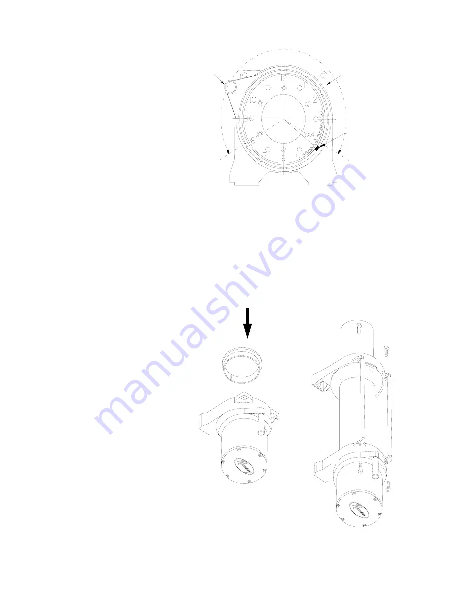
5.  Determine position shifter knob needs to 

be for your application. 

Note: 

Shifter 

knob cannot be positioned too low or it 
will interfere with the feet on the Gear 
End Bearing (see Range of Position in 
Figure 8). 

6.  To position the shifter knob, place lock-

ing ring in end bearing with stop post 

approximately 180° from where shifter 
knob needs to be positioned. Place cam 
ring over locking ring in proper position 
and confirm that shifter knob will move 
from engaged to disengaged position 
without interference. Mark position of 
stop post on end bearing. 

 
7.  Remove cam ring and locking ring from end bearing. Insert springs (item #39) into end bearing. When you replace the 

locking ring (item #35) over the springs, be sure the springs compress down into their recesses, and don’t bend side-
ways.  

8.  Reassemble Gear Housing as shown in Figure 7. Make sure locking ring is positioned with stop post at marked loca-

tion. The capscrews (item #22) for the retainer should be tightened to 40-45 in-lbs. 

Do not over-tighten.


9.  Place Gear Housing over the stacked gears, etc. that you removed in step 3. Gently work the housing over the stack, 

turning it as needed to mesh the planetary gears with the ring gear in the housing. Once they are all in the housing, flip 
the assembly over. Align the Gear Housing Cover and gasket with the holes in the ring gear. Replace the (6) capscrews 
that hold the Gear Housing Cover onto the Gear Housing. Tighten securely. 

10.  Move the Shifter to the Disengaged position. 
11.  Turn the Gear Housing over and set it on the 

work bench with the Gear Housing Cover 
down. See Figure 9.  

12.  Install the drum bushing into the Gear Hous-

ing, confirming that the slot in the bushing is 
aligned with the key in the end bearing. Pick 
up the rest of the winch (drum and motor 
end), and holding the drum, lower the winch 
onto the gear end. Stab the shaft into the 
gear end--you may need to turn the drum 
slightly to get the shaft to go all the way in. 

13.  Place the tiebars on the motor end and gear 

end and fasten using (4) screws. Tighten 
securely. 

14.  Once the winch is reassembled, turn it so 

that it is sitting on its feet. Confirm that the 
cable will freespool when the shifter is in the 

Disengaged position. Connect up the winch 
temporarily and confirm that the cable 
spools when the shifter is in the Engaged 
position. 

RANGE OF POSITION

FOR SHIFTER KNOB

END BEARING

STOP POST ON

RING GEAR LOCK

CAM RING

SHIFTER

KNOB

FIGURE 8 

FIGURE 9 

Инструкция RAMSEY REP 9.5e

www.bigfoottrade.kz

Summary of Contents for REP 9.5e

Page 1: ...e there are dangers if improp erly used At the same time there are easier and faster ways for getting the job done if certain precautions are taken first Please read this manual carefully It contains...

Page 2: ...inch and repeat the procedure until all the cable except a few feet is in Disconnect the remote control switch and finish spooling in cable by rotating the drum by hand with clutch disengaged On hidde...

Page 3: ...itional protection Use the vehicle wheel power to help the winch but don t over take the winch line Plan your pull You can t always hook up and pull out in one step Examine all the areas for anchoring...

Page 4: ...ed motor leads coming from solenoid assembly to appropriately marked motor ter minals TIGHTEN NUTS ON MOTOR TERMINALS SECURELY see FIGURE 3 Attach solenoid ground wire to grounding bolt located at bot...

Page 5: ...fore reversing To actuate winch simply plug remote control switch into receptacle in black solenoid cover of winch Run winch forward and reverse to check connection and to determine winch operating di...

Page 6: ...sembly or the end of the drum Set aside 2 Remove 6 capscrews from the Gear Housing Cover Holding the Gear Housing Cover over the Gear Housing assem bly flip it over and set it on the workbench 3 Gentl...

Page 7: ...t as needed to mesh the planetary gears with the ring gear in the housing Once they are all in the housing flip the assembly over Align the Gear Housing Cover and gasket with the holes in the ring gea...

Page 8: ...cable drum flange Before installing the new cable assembly make sure end of cable is squarely cut and wrapped with tape to prevent fray ing Form a short 90 bend approximately long in the end of the ca...

Page 9: ...t should make an audible click when energized 2 Defective remote control switch 2 Disengage winch clutch remove remote control switch plug from the socket and jump pins at 8 and 4 o clock Motor should...

Page 10: ...9 Motor Assembly 30 1 442219 Gasket Ring Gear 10 1 328138 Cover Gear Housing 31 1 444077 Gear Ring Input 11 1 332193 Drum Cable 32 1 448046 Cable Anchor 12 1 334147 Gear Intermediate Sun 33 2 448049 T...

Page 11: ...4Lg Hx Hd Z P 11 7 416216 Screw 10 24NCX 1 2 Lg Rd Hd Z P 12 2 416227 Screw 10 24NCX 3 4 Lg Truss Hd Black 13 6 418004 Nut Hx Reg 10 24NC Z P 14 6 418014 Nut Hx Reg 1 4 20NC Z P 16 3 418140 Washer 10...

Page 12: ...charges in connection with the replacement or repair of defective parts nor shall it apply to a product upon which repairs or alterations have been made unless authorized by the manufacturer or for e...

Reviews: