background image


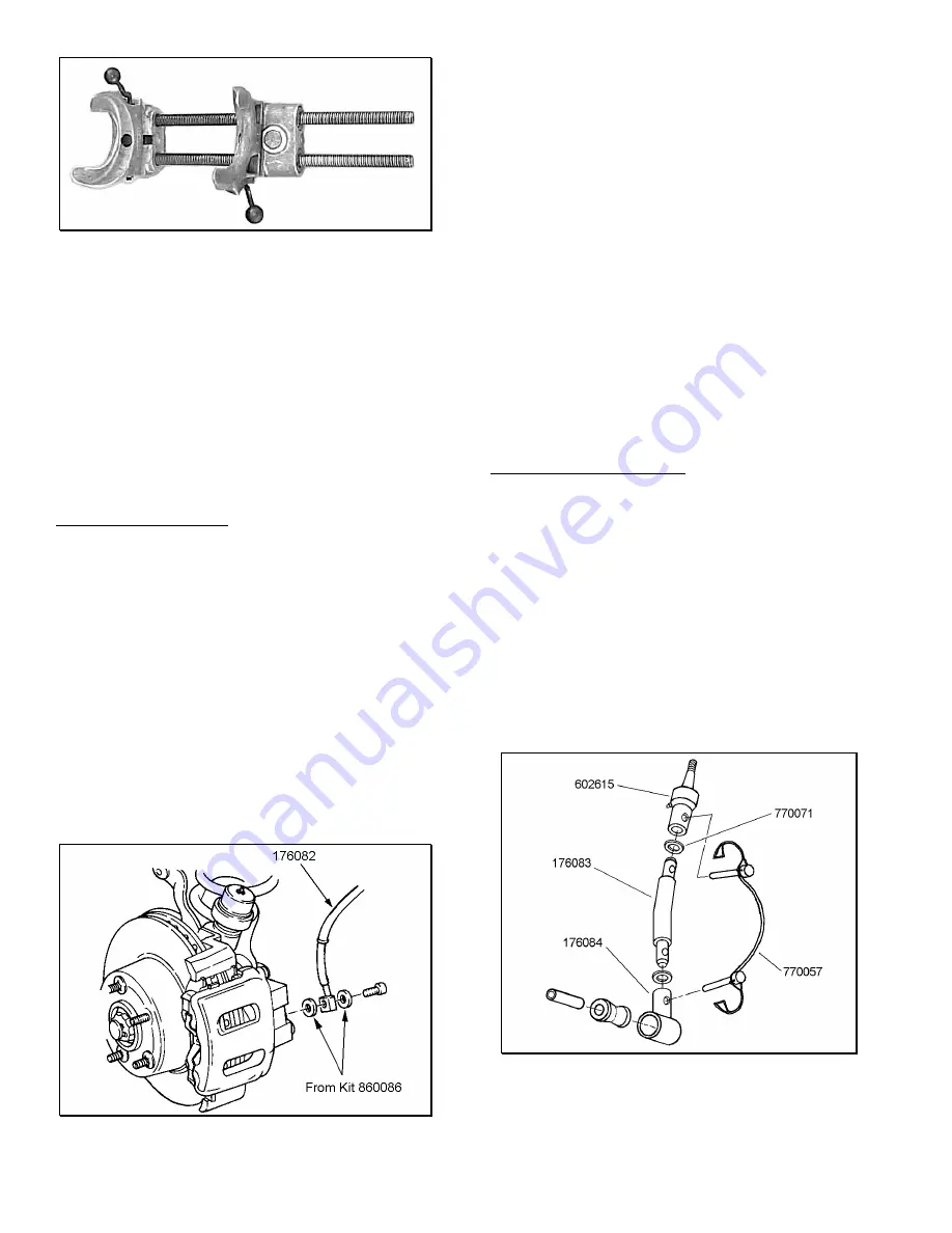
Figure 7 

 
4)


…

 Place bump stop perch 176089 inside the 

compressed spring as you install the spring into the upper 
and lower spring pockets.  Carefully remove the spring 
compressor. 
 
5)


…

 Rotate spring so pig tail end fits back in spring 

pocket.  Attach the bump stop perch to the axle pad with the 
self-tapping screw from kit 860157. 
 
6)


…

 Repeat steps 2 through 5 for other side. 


B

RAKE 

H

OSE 

R

EPLACEMENT


NOTE:  To keep the brake bleeding process to just the front 
calipers, do not allow the brake fluid to drain completely from 
the master cylinder reservoir. 
 
1)


…

 Separate the left front brake hose from the brake 

tube and the frame rail.  Plug tube to prevent brake fluid 
leakage. 
 
2)


…

 Remove the brake hose from the caliper.  Discard 

copper washers. 
 
3)


…

 Attach left brake hose RS170082 to the caliper with 

NEW copper washers from kit RS860086, and the original 
bolt.  See figure 8.  Tighten the bolt to 23 ft.-lbs. 


Figure 8 

4)


Attach the new brake hose to the frame and brake 

tube.  Tighten securely. 
 
5)


Repeat steps 1 through 4 to install right front brake 

hose RS170081. 


Refill the master cylinder reservoir with approved 
brake fluid and bleed the front brakes as follows: 


Attach a clear hose to the right front caliper bleeder screw 
and immerse the other end into a container of clean brake 
fluid. 


Loosen the bleeder valve on the caliper. 


Have an assistant push the brake pedal down and then 
hold. 


Tighten the bleeder valve and slowly release the pedal. 


Repeat the procedure until all air is purged from the 
caliper. 


Attach the hose and container to the left front caliper and 
repeat the bleeding process.  Refill the brake master 
cylinder reservoir as necessary. 


S

WAY 

B

AR 

E

ND 

L

INK 

A

SSEMBLY


1)


…

 Apply silicone lubricant and press a bushing from kit 

860561 into a front end link bottom socket (176084). 
 
2)


…

 Apply silicone lubricant and press a sleeve from kit 

860561 into the installed bushing. 
 
3)


…

 Install a rubber washer from kit 860561 onto each 

end of center section 176083. 
 
4)


…

 Connect the bottom socket assembly to a top swivel 

(602615) with the center section.  Insert a set of locking pins 
(770057) as shown in figure 9. 


Figure 9 

 
5)


…

 Grease the top swivel.  Push down on the ball stud 

when applying grease for the first time.  Stop when grease 
flows past ball. 

  6

Summary of Contents for RS6505

Page 1: ...alignment must be within factory specifications and the frame must be sound no cracks damage or corrosion F Unless otherwise specified tighten all bolts to the standard torque specifications listed at the end of the note s section Do not use an impact wrench to tighten any of these bolts They tend to over tighten smaller bolts and under tighten larger bolts USE A TORQUE WRENCH B Do not install a b...

Page 2: ... using the following tire and wheel combination 33 x 12 50R 15 tire 15 x 8 wheel with 3 75 of wheel backspacing Before installing any other combination consult your local tire and wheel specialist O To reduce rear driveline vibration and or to increase ground clearance you may want to install a double cardan driveshaft and not use the skid plate crossmember spacers and shift relocating bracket A d...

Page 3: ...hread Lock 2 860161 Skid Plate Spacer Kit 1 176091 Skid Plate Spacer 6 176092 Skid Plate Shim 6 1 2 Cone Washer 6 1 2 13x2 5 FSHCS 6 M10 1 50x70 HHCS 2 10mm Lock Washer 2 860218 Articulation Bushing Kit 1 420080 Sleeve 8 520080 Bushing 16 860070 Shim Kit 1 Washer 16 860483 Skid Plate Hardware Kit 1 M12 1 75 x 65 HHCS 6 12mm Washer 6 860561 Quick Disconnect Hardware Kit 1 420084 Sleeve Front End Li...

Page 4: ...tainer and grommet from both front shock absorbers 6 If applicable remove the bolts attaching the automatic transmission skid plate to the frame rails and the transfer case crossmember Do not use an impact wrench Remove the skid plate NOTE To reinstall the automatic transmission skid plate an adapter kit must be purchased separately 7 Raise the front of the vehicle and support the frame with jack ...

Page 5: ... cotter pin and nut from the drag link at the pitman arm Separate the drag link ball stud from the pitman arm with a puller tool Do not use a pickle fork 2 Center the steering wheel and mark the position of the original pitman arm Remove the nut and washer from the steering gear shaft 3 Remove the pitman arm from the steering gear with pitman arm puller C 4150 A 4 Align and install new pitman arm ...

Page 6: ...right front brake hose RS170081 Refill the master cylinder reservoir with approved brake fluid and bleed the front brakes as follows Attach a clear hose to the right front caliper bleeder screw and immerse the other end into a container of clean brake fluid Loosen the bleeder valve on the caliper Have an assistant push the brake pedal down and then hold Tighten the bleeder valve and slowly release...

Page 7: ...mounting hole Install upper shock grommet retainer and nut Tighten to 17 FT LBS Repeat for other side Figure 11 11 Tighten the sway bar lower link bolts to 70 FT LBS 12 Tighten the lower suspension arm to frame bracket nut and bolt to 130 FT LBS both sides 13 Align the reference marks on the adjustment cams and lower arm axle brackets Tighten nuts to 85 FT LBS 14 Apply grease to the new lower susp...

Page 8: ...DO NOT REUSE ORIGINAL SHOCK ABSORBERS 2 Remove the lower arm axle and frame mounting bolts Remove the lower suspension arm 3 Install new Rancho cast link 176180 along with four shims from kit 860070 to the frame and axle brackets See figure 13 Use original hardware but do not tighten 6 Mark the orientation of the coil springs on the axle pads Carefully lower the rear axle until the coil springs ar...

Page 9: ...gure 14 5 Place the track bar into the frame bracket and install the original hardware Tighten the track bar mounting bolts to 74 ft lbs 3 Repeat steps 1 2 for other side 4 Lower rear axle and position the new coil springs onto the axle pads Align springs with reference marks Raise the axle until the springs seat in the upper mounts 6 Tighten all lower arm pivot bolts to 130 ft lbs and the shock a...

Page 10: ... washer and apply thread lock to 3 flat head screws from kit 860161 Insert the screws through the crossmember spacers and into the frame See figure 17 3 Slide the torque shaft bracket off the torque shaft and remove the bearing plate gasket 4 Attach the bearing plate with gasket to shift relocating bracket 176090 as shown in figure 20 5 Using bracket 176090 as a template mark the two mounting hole...

Page 11: ...into 4L position and loosen lock bolt on adjusting trunnion 7 Reposition the cover boot Install one screw on the left side or 9 o clock position NOTE Be sure shift rod slides freely in trunnion 8 Rotate the boot clockwise to match the increased floor pan opening Mark and drill the three new mounting holes See figure 22 9 Verify that transfer case range lever is fully engaged in 4L position Tighten...

Page 12: ...s for full suspension movement Figure 23 4 Readjust headlamps Have vehicle Aligned to manufacturer s specifications IMPORTANT NOTICE WARNING DO NOT OPERATE THIS VEHICLE ON PUBLIC ROADS OR AT SPEEDS GREATER THAN 15 MPH WITH THE SWAY BAR END LINKS DISCONNECTED Alignment Specifications Adjustment Preferred Range Caster 7 1 0 Camber fixed angle 0 25 0 63 Toe In each wheel 0 15 0 15 Thrust Angle 0 0 15...

Reviews: