10
6)
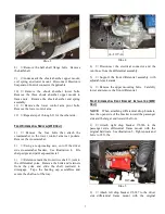
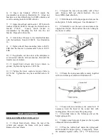
Note the number of exposed threads on the
inner tie rod and remove outer tie rod end. Install new
tie rod end 602617 to the same location.
7)
Attach tie rod end 602617 to steering knuckle
176475 with the supplied nut. Tighten ball stud nut to
33 ft. lbs. Tighten jam nut to 22 ft. lbs.
Illus. 12
8)
Repeat steps 1 through 7 to install the half
shaft, outer tie rod end and right steering knuckle
176476 on the passenger side.
S
WAY
B
AR
D
ROP
B
RACKET
I
NSTALLATION
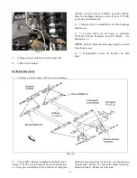
1)
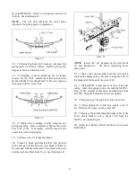
Using the washers and shorter bolts from
hardware kit 860547, attach the sway bar drop
brackets (176579) to the frame rails at the original
sway bar location. Face open side of bracket inward.
2)
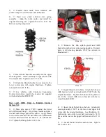
Using the washers and longer bolts from
hardware kit 860547, attach the sway bar to drop
brackets 176579. Tighten mounting bolts to 45 ft. lbs.
Illus. 13
3)
Loosely attach the sway bar to the lower
control arms with the original end link assemblies.
B
RAKE
H
OSE
I
NSTALLATION
1)
Install the brake rotor. Apply thread lock and
attach the caliper to the knuckle with the original
mounting bolts. Tighten the caliper mounting bolts to
129 ft. lbs.
2)
Disconnect the brake tube from the hose at the
frame rail. Plug tube to prevent brake fluid seepage.
3)
Remove the retainer clip and disconnect the
brake hose from the caliper. Discard copper washers.
If necessary, cut-off washer from bolt.
4)
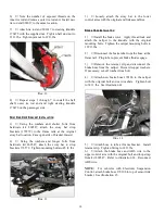
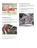
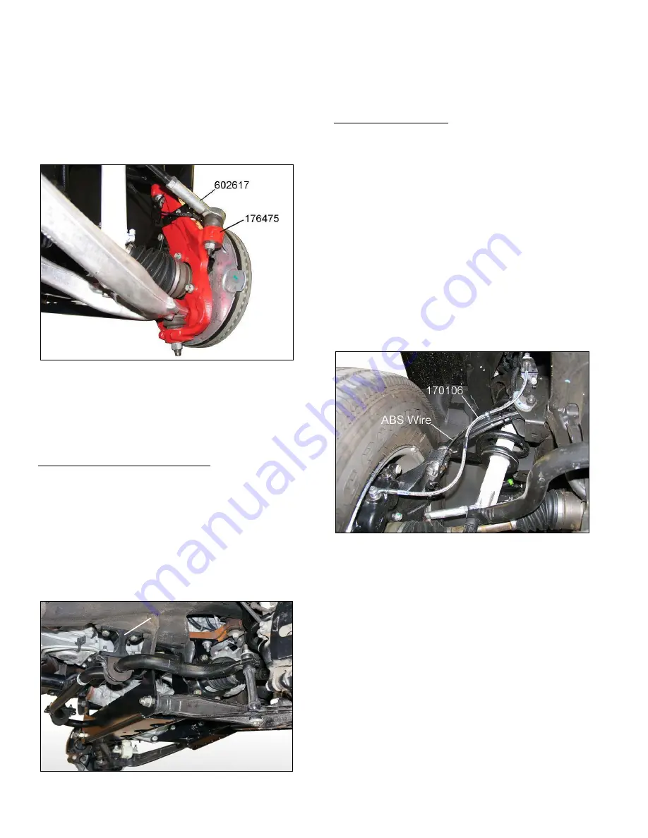
Attach new brake hose 170106 to the caliper
with the original bolt and new washers. Tighten bolt
to 38 ft. lbs. See illustration 14.
Illus. 14
5)
Attach hose to tube at frame bracket. Install
retainer clip. Tighten fitting to 18 ft. lbs.
6)
Attach the brake hose and ABS wire to the
upper control arm with the original bolt and loop strap
from kit 860547. Refer to illustration 14. Reconnect
ABS wire.
NOTE: For vehicles with Electronic Suspension
Control, attach brake hose 170106 to top of sensor link
bracket. See illustration 15.
176579


