2
READ ALL INSTRUCTIONS THOROUGHLY FROM START TO FINISH BEFORE BEGINNING INSTALLATION
IMPORTANT NOTES!
WARNING:
This suspension system will enhance the off-
road performance of your vehicle. It will handle differently,
both on and off-road, from a factory equipped passenger car
or truck. Extreme care must be used to prevent loss of
control or vehicle rollover during abrupt maneuvers. Failure
to drive this vehicle safely may result in serious injury or
death to the driver and passengers. ALWAYS WEAR your
seat belts, REDUCE your speed, and AVOID sharp turns
and other abrupt maneuvers.
A.
To reduce front drive shaft vibration, a replacement
shaft (part No. 3194-9824) is available from: POWERTRAIN
INDUSTRIES 7532 Anthony Avenue, Garden Grove, CA
92841 1-800 798-4585. For vehicles equipped with the
Autoride (Air) Suspension Option,
front shock
RS99799
and rear relocator kit
RS6202
must be installed.
B.
Before installing this system, have the vehicle’s
alignment and frame checked by a certified technician. The
alignment must be within factory specifications and the
frame of the vehicle must be sound (no cracks, damage or
corrosion).
C.
Do not install a body lift kit with this suspension system
or interchange Rancho components with parts from another
manufacturer. New Rancho shock absorbers are required
and must be purchased separately. Front shocks:
RS999786 or RS999799, Rear shocks: RS999297
D.
Do not powdercoat, chrome, cadmium, or zinc plate any
of the components in this system. To change the
appearance of components, enamel paint can be applied
over the original coating.
E.
Welding on a car creates an electrical charge
throughout the body and frame. Disconnect the vehicle’s
battery prior to any welding. Place welding ground clamps
as near as possible to the weld. When welding on the
frame, never use a vehicle suspension component as a
welding ground point.
F.
Each hardware kit in this system contains fasteners of
high strength and specific size. Do not mix hardware kits or
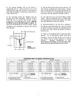
substitute a fastener of lesser strength. See bolt
identification table on page 2.
G.
Compare the contents of this system with the parts list
in these instructions. If any parts are missing, contact the
Rancho Technical Department at 1-734-384-7804.
H.
Install all nuts and bolts with a flat washer. When both
SAE (small OD) and USS (large OD) washers are used in a
fastener assembly, place the USS washer against the
slotted hole and the SAE washer against the round hole.
I.
Apply a drop of thread locking compound to all bolts
during installation. CAUTION: Thread locking compound
may irritate sensitive skin. Read warning label on container
before use.
J.
Unless otherwise specified, tighten all nuts and bolts to
the standard torque specifications shown in the table below.
USE A TORQUE WRENCH for accurate measurements.
K.
Some of the service procedures require the use of
special tools designed for specific procedures. The following
tools and supplies are recommended for proper installation
of this system:
Chevrolet Service Manual
Coil Spring Compressor
Die Grinder
Drill motor
Assorted Drills: 1/8" through 1/2"
Torque Wrench (250 FT-LB capacity)
1/2” Drive Ratchet and Sockets
Assorted Combination Wrenches
Heavy Duty Jack Stands
Wheel Chocks (wooden blocks)
Hydraulic Floor Jack
Center punch
File
Reciprocating Saw (to modify frame)
Hammer
Wire Brush (to clean bracket mounting surfaces)
Silicone Spray Lubricant
Brake fluid
Tape Measure
Safety Glasses
(wear safety glasses at all times)
L.
It is extremely important to replace torsion bars, CV
flanges, and front drive shaft/pinion relationships as original.
Be sure to mark left/right, front/rear, and indexing of mating
parts before disassembly. A paint marker or light colored
nail polish is handy for this.
M.
Suspension components that use rubber or urethane
bushings should be tightened with the vehicle at normal ride
height. This will prevent premature failure of the bushing
and maintain ride comfort.


