6
FRONT SUSPENSION
V
EHICLE
P
REPARATION
&
S
WAY
B
AR
R
EMOVAL
1)
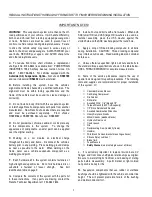
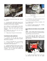
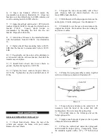
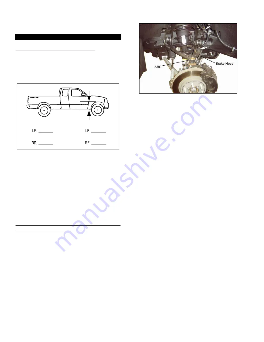
Park the vehicle on a level surface. Set the
parking brake and chock rear wheels. Measure and
record the distance from the center of each wheel to
the top of the fender opening. See illustration #1.
Illus. 1
2)
Raise the front of the vehicle and support the
frame with jackstands. Remove the front wheels and
set them aside.
3)
Disconnect the sway bar from the lower
control arms. Save end links for reuse.
4)
Remove the sway bar frame bracket bolts.
Remove the sway bar.
S
TEERING
K
NUCKLE
,
S
HOCK
A
BSORBER
,
H
ALF
S
HAFT
(4WD
O
NLY
),
&
L
OWER
C
ONTROL
A
RM
R
EMOVAL
1)
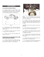
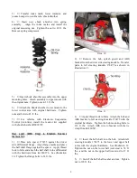
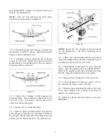
Remove the brake hose and ABS sensor wire
from the upper control arm. Disconnect the ABS
sensor wire at the frame rail. See illustration 2.
Illus. 2
NOTE: For vehicles equipped with Electronic
Suspension Control (Autoride), separate brake hose
from sensor link bracket.
2)
Remove the brake caliper anchor bolts.
Remove the brake caliper and its mounting bracket as
an assembly. Hang the caliper assembly with wire or a
tie wrap.
CAUTION: Do not allow the caliper to hang by the
brake hose.
3)
Label the brake rotor left or right. Remove the
brake rotor. Remove the half shaft axle nut.
4)
Remove the nut from the outer tie rod stud.
Lightly tap the steering knuckle and disconnect the tie
rod end from the knuckle.
5)
Loosen the nuts at the upper and lower ball
joints. Lightly tap the steering knuckle to disconnect
the ball joints.
6)
Remove the upper and lower ball joint nuts.
Carefully remove the steering knuckle.
7)
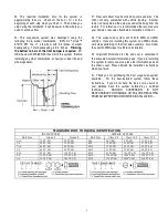
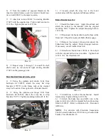
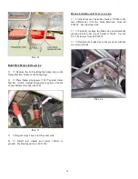
Index mark the half shaft and front differential
flange for installation reference. See illustration 3.


