8
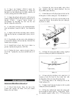
hardware. See illustration 6. Tighten bolts to 65 ft.
lbs.
Illus. 6
3)
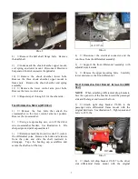
With the help of an assistant, loosely attach the
front differential to the installed drop brackets with the
hardware from kit 860550. Refer to illustration 6.
Install the larger USS washers on the passenger side.
4)
Push the differential assembly toward the
passenger side. Tighten the nuts and bolts to 65 ft. lbs.
NOTE: Verify that the front differential does not
contact the driver side rear frame bracket of the lower
control
arm.
FAILURE
TO
PROVIDE
CLEARANCE COULD CAUSE DAMAGE TO
THE FRONT DIFFERENTIAL ASSEMBLY.
5)
Reattach the electrical connector and vent
hose.
6)
Align reference marks and reattach the front
drive shaft U-joint to the differential yoke. Tighten
bolts to 22 ft. lbs.
S
UBFRAME
I
NSTALLATION
1)
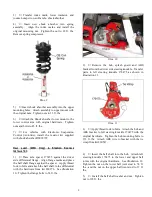
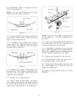
Using a round file, enlarge the inside corners
of both lower control arm front brackets. See
illustration 7.
Illus. 7
2)
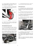
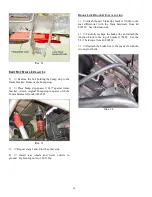
With the help of an assistant, raise the
subframe up into the lower control arm frame brackets.
Attach the subframe to the brackets with the original
hardware. See illustration 8. Tighten the subframe to
bracket bolts to 107 ft. lbs.
3)
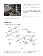
Loosely attach the lower control arms to the
subframe with the hardware from kit 860546.
Illus. 8
C
OIL
S
PRING
&
S
HOCK
A
BSORBER
I
NSTALLATION
NOTE: New shock absorbers are not included with
this kit and must be purchased separately. See
Important Notes A and C.
1)
Using a quality spring compressor, compress
the coil spring until the tension is released from the
shock absorber.
2)
Remove the upper mounting nut. Slide the
shock absorber out of the spring assembly.


