9
3)
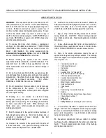
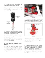
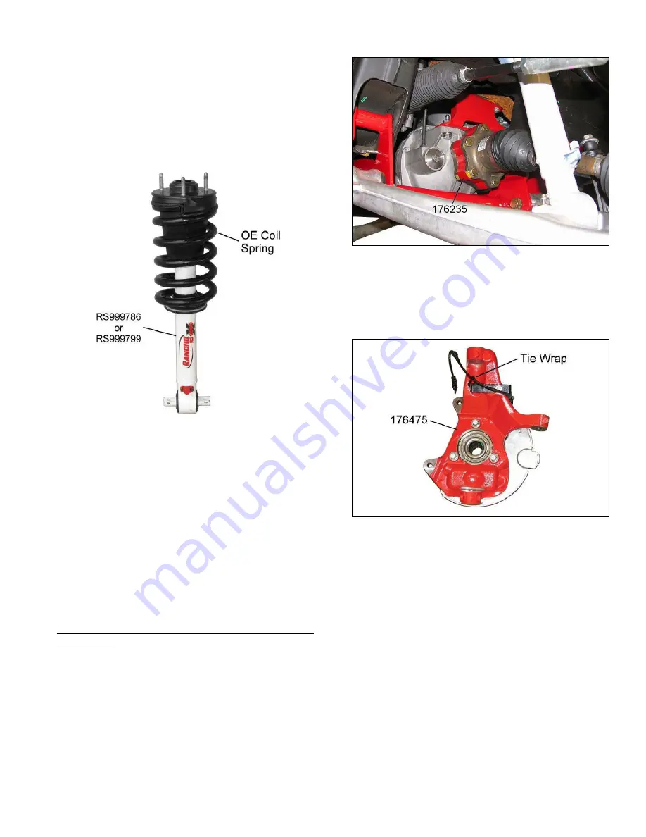
Transfer index mark, lower insulator, and
jounce bumper to new Rancho shock absorber.
4)
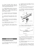
Insert new shock absorber into spring
assembly. Align the index marks and install the
original mounting nut. Tighten the nut to 22 ft. lbs.
Remove spring compressor.
Illus. 9
5)
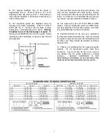
Insert shock absorber assembly into the upper
mounting holes. Attach assembly to upper mount with
the original nuts. Tighten nuts to 33 ft. lbs.
6)
Attach the Shock absorber lower mount to the
lower control arm with original hardware. Tighten
nuts and bolts to 45 ft. lbs.
7)
For vehicles with Electronic Suspension
Control (Autoride), install the resistor kit supplied
with shock absorber RS999799.
H
ALF
SHAFT
(4WD Only)
&
S
TEERING
K
NUCKLE
I
NSTALLATION
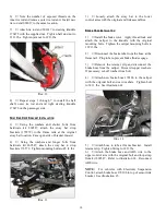
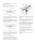
1)
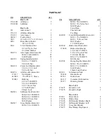
Place axle spacer 176235 against the driver
side differential flange. Align flange marks and place
the half shaft flange against the spacer. Apply thread
lock to bolts and attach the half shaft to the differential
with the hardware from kit 860176. See illustration
10. Tighten the flange bolts to 58 ft. lbs.
Illus. 10
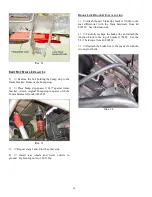
2)
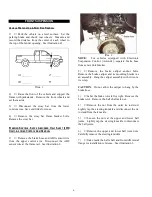
Remove the hub, splash guard and ABS
bracket from the driver side steering knuckle. Transfer
parts to left steering knuckle 176475 as shown in
illustration 11.
Illus. 11
3)
Apply thread lock to bolts. Attach the hub and
ABS bracket to left steering knuckle 176475 with the
original hardware. Tighten the hub mounting bolts to
133 ft. lbs. Attach ABS wire to bracket with the tie
wrap from kit 860547.
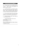
4)
Insert the half shaft into the hub. Attach left
steering knuckle 176475 to the lower and upper ball
joints with the original hardware. See illustration 12.
Tighten the nut on the lower ball joint stud to 74 ft.
lbs., and the nut on the upper ball joint stud to 37 ft.
lbs.
5)
Install the half shaft washer and nut. Tighten
nut to 165 ft. lbs.


