53
6. INSTALLATION
7KH DSSOLDQFH LV RQO\ WR EH LQVWDOOHG LQ ORFDWLRQV
where use and maintenance is restricted to trained
personnel.
7KHPDFKLQHVDUH¿WWHGZLWKKHLJKWDGMXVWDEOHIHHW
RQO\UHDU
7KHVXSSRUWVXUIDFHVKDOOEHOHYHOOHGGU\VPRRWK
VWHDG\DQGVWDEOHDQGDWVXFKDKHLJKWWKDWWKHFXS
warming surface is at over 150 cm from ground. Do
not use water jets or install where water jets are
used.
In order to guarantee normal operation, the machine
must be installed in areas that the environmental
temperature is between +5°C
y
&HQGKXPLGLW\
of not over 70%.
It does not need to be anchored to the surface and it
GRHVQRWUHTXLUHDQ\WHFKQLFDORSHUDWLRQVWRGDPSHQ
YLEUDWLRQVLQRUGHUWRRSHUDWHSURSHUO\
4.1. precautionary measures
7KLVPDFKLQHPD\RQO\EHXVHGZLWKIRRGVWXIIV,W
FDQQRWEHXVHGIRUKHDWLQJOLTXLGVRUJULQGLQJDQ\RWKHU
kind of product that could damage and pollute it.
The manufacturer cannot be held responsible
for damage to people or things caused by
unsuitable, erroneous or irrational use.
5. TRANSPORT
5.1. Packaging
The machine is delivered in a strong cardboard box
with internal protection.
7KHSDFNDJLQJEHDUVV\PEROVZKLFKPXVWEHREVHU
-
ved during handling and stocking of the item.
Always keep the package in a vertical position
during transport. Do not turn it over or lay it
on its side and avoid bumping and exposure
to atmospheric agents.
5.2. Inspection on receipt
Check that the machine received corresponds to
WKHRQHLQGLFDWHGRQWKHGHOLYHU\QRWHLQFOXGLQJDQ\
accessories.
Check that it has not been damaged during transport
and, if so, inform the forwarder and our customer
VHUYLFHRI¿FHLPPHGLDWHO\
The packing elements (plastic bags, expan-
ded polystyrene, nails, cardboard, etc.) must
not be left within reach of children as they are
potential sources of danger. Do not dispose
of the packing elements in the environment;
FRQVLJQ WKHP WR ¿UPV DXWKRUL]HG IRU WKHLU
disposal.
It is recommended to leave the area around the ma-
chine free to facilitate its use and the performance
RIDQ\PDLQWHQDQFHRSHUDWLRQV
,IWKHPDFKLQHLVZHWRUYHU\GDPSZDLWXQWLOLWLV
FRPSOHWHO\ GU\ EHIRUH LQVWDOOLQJ RU XVLQJ LW ,W LV
DOZD\VQHFHVVDU\WRUHTXHVWDQDFFXUDWHFRQWUROWR
TXDOL¿HGVHUYLFHSHRSOHLQRUGHUWR¿QGDQ\SRVVLEOH
damage to the electric components.
Reserve an area near the machine for the installa-
tion of the coffee grinding and dosage machine (see
relevant documentation).
7KHPDFKLQHLVXVXDOO\HTXLSSHGZLWKDZDWHUVRI
-
WHQHUW\SH'3RU'3ZKLFKPXVWEHFRQQHFWHG
E\ WKH XVHU LQ FRPSOLDQFH ZLWK WKH ODZV LQ IRUFH
Should a different softener be installed, refer to the
documentation of the relevant product.
A dreg drawer should be fitted by the installer.
6.1. Connections to be made by the
user.
Hook-up must be carried out by qualified
personnel in full accordance with federal,
state and local regulations.
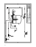
6.1.1. Water supply (Mod.E1 - S1)
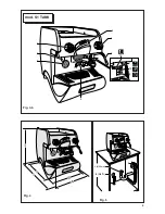
(Fig.5)
This equipment is to be installed to comply
with the applicable federal, state or local
plumbing codes.
Connections must be installed close to the machine.
L
Water drainage pipe 1, having a minimum internal
diameter of 30 mm, equipped with a water-trap
accessible for inspection.
L
:DWHUVXSSO\SLSHZLWKD*FXWRIIWDS
Make sure that the maximum supply pressu-
re does not exceed 6.5 bar; otherwise, install
a pressure reducer.
6.1.2. Electric supply
7KHPDFKLQHLVVXSSOLHGUHDG\IRUFRQQHFWLRQDFFRU
-
GLQJWRWKHUHTXLUHGHOHFWULFDOVSHFL¿FDWLRQV
Before connecting the machine ensure that the
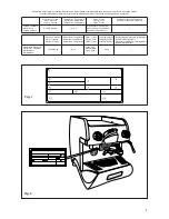
SODWHGHWDLOV¿JFRPSO\ZLWKWKRVHRIWKHHOHFWULF
distribution network.
7KH HOHFWULFDO FRQQHFWLRQ FDEOH PXVW EH GLUHFWO\
connected to the connection provided according to
FXUUHQWOHJLVODWLRQ(QVXUHWKDWWKHHDUWKLQJV\VWHP
LVHI¿FLHQWDQGLQFRPSOLDQFHZLWKFXUUHQWOHJDOUH
-
quirements.
7KHHDUWKLQJV\VWHPDQGWKHOLJKWHQLQJSURWHFWLRQ
V\VWHP PXVW EH UHDOL]HG LQ DFFRUGDQFH ZLWK WKH
provisions of current legislation.
)RUWKHVXSSO\QHWZRUNXVHDFDEOHLQFRPSOLDQFHZLWK
standards with protective conductor (earthing wire).
)RUVLQJOHSKDVHSRZHUVXSSO\XVHDFDEOHZLWK
conductors (phase + n earth).
Summary of Contents for EPOCA E
Page 4: ......
Page 6: ......
Page 8: ...8 1 2 3 4 5 6 8 7 9 10 mod S1 Fig 3 a 1 2 3 4 5 6 8 7 9 10 mod E1 Fig 3...
Page 9: ...9 Fig 4 Fig 5 4 L o v a t o L 2 3 8 G 1 30mm 1 2 3 4 5 6 8 7 9 10 12 mod S1 TANK Fig 3 b...
Page 10: ...10 4 mod S1 TANK 3 A B C D E 6 5 7 mod E1 S1 mod S1 TANK 1 2 2 8 8 9 1 Fig 6...
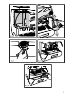
Page 11: ...11 1 2 A B C Fig 7 Fig 8 Fig 9 Fig 10 Fig 11...
Page 12: ...12 1 2 Fig 12 B C 2 1 Fig 13...
Page 35: ......

