54
7. OPERATION
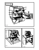
7.1. Controls
(Fig.6)
1 Main switch.
Two-position switch with led.
Turn on the switch, led on, the machine is turned
(apart from the boiler) and the pump is turned on
WR¿OOWKHERLOHU
2 Boiler resistance switch.
Two-position switch with led.
On activating the switch, the led comes on, and
power is supplied to the resistance for the boiler
water.
3 Coffee dispenser switch
(mod. S1 - S1 TANK)
On pressing the button, continuous coffee dispen-
sing begins and the led comes on.
2QUHSUHVVLQJWKHVZLWFKWKHFRIIHHGHOLYHU\VWRSV
and the led goes out.
4 Electronic coffee delivery button panel.
(mod.
E1). Five buttons with relative led:
A
Press the button for a second, led on, release
EXWWRQDVPDOOFRIIHHLVGLVSHQVHG
The led turns off and dispensing ceases.
B
Press the button for a second, led on, release
WKHEXWWRQWZRVPDOOFRIIHHVDUGLVSHQVHGIURP
the same unit.
The led turns off and dispensing ceases.
C
Press the button for a second, led on, release
WKHEXWWRQDELJFXSRIFRIIHHLVGLVSHQVHG
The led turns off and dispensing ceases.
D
Press the button for a second, led on, release
WKHEXWWRQWZRELJFXSVRIFRIIHHDUHGLVSHQVHG
from the same unit.
The led turns off and dispensing ceases.
E
Press the button for a second, led on, release
WKHEXWWRQFRIIHHLVFRQWLQXRXVO\GLVSHQVHG
Press the button for a second, led off, release
EXWWRQFRQWLQXRXVGLVSHQVLQJRIFRIIHHFHDVHV
7RLQWHUUXSWGLVSHQVLQJWDNLQJSODFHE\SUHVVLQJ
A-B-C-D
, hold button
E
down until the relative
led turns off.
5 Hot water supply tap
Tap: turn in an anticlockwise direction to open and
clockwise to close.
6 Steam supply handwheel.
Tap: turn in an anticlockwise direction to open and
clockwise to close.
7.2. Control instruments
(Fig.6)
7 Gauge
ZLWKPRELOHQHHGOHRQD¿[HGGLDOZLWKD
scale and colour indicator areas.
Visual control of the boiler pressure.
8 Boiler water level indicator
9 Tank water level indicator
(Mod.S1 TANK)
6.2. Connections
L
Place the machine on the horizontal sur-
IDFHSUHYLRXVO\SUHSDUHG
%HIRUHFRQQHFWLQJWKRURXJKO\ZDVKWKHPDLQVZDWHU
pipes:
L
/HDYHWKHZDWHUVXSSO\WDSVUXQQLQJDWIXOOSUHV
-
sure for several minutes.
L
&RQQHFWWRWKHPDLQVZDWHUVXSSO\
L
Connect the machine to the socket.
7KRURXJKO\ZDVKDOOWKHZDWHUSLSHVRIWKHPDFKLQH
L
/HDYHWKHZDWHUVXSSO\WDSVUXQQLQJDWIXOOSUHV
-
sure.
L
6ZLWFKRQPDLQVZLWFKZDLWXQWLOWKHERLOHU¿OOV
up to the level set.
L
Switch on main switch 2 to begin heating the water
in the boiler.
L
Operate each unit in order to allow the water to
HVFDSHIRUDERXWRQHPLQXWHUHSHDWWKHRSHUDWLRQ
twice.
L
Deliver steam from the steam jets for about one
minute.
L
'HOLYHUKRWZDWHUIRUDERXWRQHPLQXWHUHSHDWWKH
operation twice.
L
Switch off switches 1 and 2.
L
(PSW\WKHZDWHUIURPWKHERLOHUVHHSRLQW
IMPORTANT
Should the machine not deliver water for over
24 hours, wash the internal components be-
fore beginning work, repeating the operations
as described above
ATTENTION
Please be informed that in order to avoid
SUHVVXUHIDOOVGXULQJWKHERLOHU¿OOLQJZH¿WWHG
LQWRWKH¿OOLQJVROHQRLGYDOYHDUHVWULSWLRQ
1.25 mm.
If, during the installation, the machino get in
security mode (the on/off selection on the
WRXFKSDGZLOOÀDVKUHVHWWKHPDFKLQHXVLQJ
the main switch.
,QERWKFDVHVLWLVQHFHVVDU\WRSURYLGHDQDXWRPDWLF
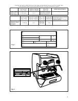
differential switch (Fig. 6) at the start of the power
cable, complete with magnetic release elements in
DFFRUGDQFHZLWKWKHLGHQWL¿FDWLRQSODWHGHWDLOV)LJ
1). The contacts must have an opening of equal or
over 3 mm and with dispersed current protection of
30 mA.
5HPHPEHUWKDWHDFKPDFKLQHPXVWEH¿WWHGZLWKLWV
RZQVDIHW\HOHPHQWV
WARNING:
Should the power supply cable be damaged
it is to be replaced by the manufacturer or by
its technical assistance service or by person
ZLWKHTXLYDOHQWTXDOL¿FDWLRQLQRUGHUWRSUH
-
vent any risks.
Summary of Contents for EPOCA E
Page 4: ......
Page 6: ......
Page 8: ...8 1 2 3 4 5 6 8 7 9 10 mod S1 Fig 3 a 1 2 3 4 5 6 8 7 9 10 mod E1 Fig 3...
Page 9: ...9 Fig 4 Fig 5 4 L o v a t o L 2 3 8 G 1 30mm 1 2 3 4 5 6 8 7 9 10 12 mod S1 TANK Fig 3 b...
Page 10: ...10 4 mod S1 TANK 3 A B C D E 6 5 7 mod E1 S1 mod S1 TANK 1 2 2 8 8 9 1 Fig 6...
Page 11: ...11 1 2 A B C Fig 7 Fig 8 Fig 9 Fig 10 Fig 11...
Page 12: ...12 1 2 Fig 12 B C 2 1 Fig 13...
Page 35: ......


