background image

58

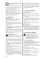
A

 = push-button panel/LED (pressing each button, 

WKHFRUUHVSRQGLQJ/('ÀDVKHV

B

 YROXPHWULFPHWHUJURXSSXOVHVXSSO\

C

 = volumetric meter group 2 

 SXOVHVXSSO\

D

 = volumetric meter group 3 

 SXOVHVXSSO\

E

 = heater level (water charge if level is not 

 VXI¿FLHQW

F

 = pressure transducer (heater resistance ON until 

heater pressure set-point is reached) 

2QO\IRUSUHGLVSRVHGPDFKLQHV
2QO\IRUPDFKLQHVZLWKVWDUUHVLVWDQFHFRQQHF

-

tion. 

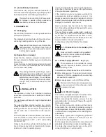
Some of the auto-test operations involve the 
dispensing of hot water and steam; take care 
in order to avoid possible burns.  

Push buttons 

A

 and 

B

¿JVFUROOGLVSOD\QXPEHUV

and letters after being positioned on the letter cor-
responding to the component to be tested. Press 

C


WRDFWLYDWH

Push-button 

D

 quits component activation.

To quit auto-test menu switch off the machine then 
switch on again.
 
Note: Press esc to quit operations 

A, E

 and 

F

During auto-test, brewing will be interrupted and the 
heater will not be fed (except for test 

F

).

10.3. Diagnostic programming

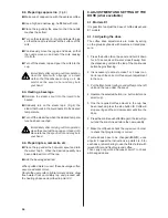
Electronic  card  E  06  allows  the  operation  of  dia-
gnostic programming with which possible machine 
failures or malfunctions can be signalled.

,QRUGHUWRXWLOLVHWKLVIXQFWLRQLWLVQHFHVVDU\WRDF

-

FHVVWKHHOHFWURQLFFDUGE\GLVPDQWOLQJWKHOHIWSDQHO

of the machine (a descriptive label of the auto-test 
function is attached to the inside of the panel).

As the use of diagnostic programming is car-
ried out on the open machine, take care not 
to touch the parts under voltage).

0DOIXQFWLRQVDUHYLVXDOLVHGRQWKHGLVSOD\VLWXDWHG

at the centre of the electronic card.
Electronic  card  E  06  allows  the  operation  of  dia-

gnostic programming with which possible machine 

failures or malfunctions can be signalled.

,QRUGHUWRXWLOLVHWKLVIXQFWLRQLWLVQHFHVVDU\WRDF

-

FHVVWKHHOHFWURQLFFDUGE\GLVPDQWOLQJWKHOHIWSDQHO

of the machine (a descriptive label of the auto-test 
function is attached to the inside of the panel).

As the use of diagnostic programming is carried out 

on the open machine, take care not to touch the parts 

under voltage).

0DOIXQFWLRQVDUHYLVXDOLVHGRQWKHGLVSOD\VLWXDWHG

at the centre of the electronic card
Possible  failures  in  course  are  indicated  on  the 

HOHFWURQLFFDUGGLVSOD\E\PHDQVRIQXPEHUVRUOHW

-

WHUVLQFDVHRIPRUHWKDQRQHIDLOXUHVLPXOWDQHRXVO\

WKH FRUUHVSRQGLQJ QXPEHUVOHWWHUV DUH DOWHUQDWHO\

GLVSOD\HG

1

 HDWHU¿OOLQJOHYHOWLPHOLPLWIRUFRUUHFW

KHDWHU¿OOLQJKDVEHHQH[FHHGHG

2

  =  Time-out  Heater  pressure  set-point:  the  time 

limit to reach heater pressure set-point has been 
exceeded 

3

 = Electronic card 12Vdc short: short circuit in the 

electronic card E 06 

4

 &DSDFLW\OHYHOVHQVRU9GFVKRUWFDSDFLW\OHYHO

VHQVRUVXSSO\KDVVKRUWFLUFXLWHG

5

 = Pressure transducer 12Vdc short: pressure tran-

VGXFHUVXSSO\KDVVKRUWFLUFXLWHG

6

 = Volumetric counter 12Vdc short: short circuit on 

WKHVXSSO\RIYROXPHWULFFRXQWHUV

7

 = 5Vdc push-button panel short: the push-button 

panel has short-circuited.

8

 = Transducer/probe short on output signal: short 

circuit on output signal from the pressure tempe-
rature probe / transducer. 

9

 = Open transducer/probe signal: the output signal 

from the temperature probe/transducer has been 
interrupted.

A

 = Absence of volumetric counter impulses group 

WKHYROXPHWULFFRXQWHURIWKH¿UVWJURXSLVQRW

transmitting impulses to the electronic card. 

B

 = Absence of volumetric counter impulses group 2: 

the volumetric counter of the second group is not 
transmitting impulses to the electronic card.  (*).

= Absence of volumetric counter impulses group 

3: the volumetric counter of the third group is not 
transmitting impulses to the electronic card (*). 

2QO\IRUSUHGLVSRVHGPDFKLQHV

7KH IDLOXUHV LGHQWLILHG E\ QXPEHUV  WR  EORFN

machine utilisation. Apart from the failure being in-

GLFDWHGRQWKHGLVSOD\WKHSXVKEXWWRQSDQHO/('

ZLOO ÀDVK VLPXOWDQHRXVO\ LQIRUPLQJ WKH XVHU RI WKH

malfunction. 
After  having  identified  and  resolved  the  failure, 

switch the machine off and then on again for normal 

utilisation. 

NOTE: 

7KHSUREOHPVLGHQWL¿HGZLWKWKHOHWWHUV

A, B


and 

C

 do not interrupt the functions of the machine. 

7KH\DUHLGHQWL¿HGRQWKHGLVSOD\DQGGXULQJGLVSHQ

-

sing from the corresponding group, the LED of the 

EXWWRQSUHVVHGZLOOÀDVK

Summary of Contents for EPOCA E

Page 1: ...K Macchina per caff Machine caf Kaffeemaschinen Coffee machine M quina para caf M quina para caf Uso e manutenzione Emploi et entretien Gebrauch und Instandhaltung Use and maintenance Uso y manutenci...

Page 2: ...Erkl rungen verst ndlich sind und dass Sie auch in Zukunft zu unseren Kunden z hlen d rfen Mit freundlichen Gr ssen Dear Customer LUVW RI DOO WKDQN RX FKRRVLQJ 5 1 2 H DUH FRQ GHQW WKDW WKH SURGXFW R...

Page 3: ...dedicated waste disposal areas Do not treat as simple urban waste RU DQ LQIRUPDWLRQ SOHDVH FRQWDFW WKH PDQXIDFWXUHU DW WKH DGGUHVV VSHFL HG LQ WKH XVHU manual The product complies with the requirement...

Page 4: ......

Page 5: ...ificada sem a nossa expressa autoriza o al quale riferita questa Dichiarazione secondo quanto prescritto dalle direttive specifiche laquelle se r f re cette d claration selon les prescriptions des dir...

Page 6: ......

Page 7: ...lt Potencia lt Pot ncia it Caldaia Chaudi re Kessel Boiler Caldera Caldeira 0 18 1 8 Mpa bar 131 2 C Acqua Vapore Eau Vapeur Wasser Dampf Water Steam Agua Vapor gua Vapor 4 Pressione Pression Druck P...

Page 8: ...8 1 2 3 4 5 6 8 7 9 10 mod S1 Fig 3 a 1 2 3 4 5 6 8 7 9 10 mod E1 Fig 3...

Page 9: ...9 Fig 4 Fig 5 4 L o v a t o L 2 3 8 G 1 30mm 1 2 3 4 5 6 8 7 9 10 12 mod S1 TANK Fig 3 b...

Page 10: ...10 4 mod S1 TANK 3 A B C D E 6 5 7 mod E1 S1 mod S1 TANK 1 2 2 8 8 9 1 Fig 6...

Page 11: ...11 1 2 A B C Fig 7 Fig 8 Fig 9 Fig 10 Fig 11...

Page 12: ...12 1 2 Fig 12 B C 2 1 Fig 13...

Page 13: ...ments and settings of the dose 56 9 1 For models E1 56 9 1 1 Adjusting the dose 56 GYDQFHG IXQFWLRQV HOHFWURQLF FDUG H 57 10 1 Heater pressure regulation from push button panel 57 10 2 Auto test compo...

Page 14: ...UN EHIRUH connecting the equipment L Adaptors multiple sockets and or extensions must not be used L In doubt request an accurate control of the plant E TXDOL HG SHUVRQQHO 7KH HOHFWULF SODQW PXVW EH SU...

Page 15: ...DQG VWDLQOHVV steel The beverages are dispensed at the front of the machine where all the buttons control devices and dispensers are to be found There is a cup warming plate on the top of the ma chin...

Page 16: ...he operator and the environment The user must not L WRXFK WKH KRW VXUIDFHV DQG GLVSHQVLQJ DUHDV L SODFH OLTXLGV FRQWDLQHUV RQ WKH PDFKLQH L SXW KLV KDQGV XQGHU WKH VSRXWV GXULQJ XVH L WUDQVSRUW WKH PD...

Page 17: ...ave the area around the ma chine free to facilitate its use and the performance RI DQ PDLQWHQDQFH RSHUDWLRQV I WKH PDFKLQH LV ZHW RU YHU GDPS ZDLW XQWLO LW LV FRPSOHWHO GU EHIRUH LQVWDOOLQJ RU XVLQJ L...

Page 18: ...sual control of the boiler pressure 8 Boiler water level indicator 9 Tank water level indicator Mod S1 TANK 6 2 Connections L Place the machine on the horizontal sur IDFH SUHYLRXVO SUHSDUHG HIRUH FRQQ...

Page 19: ...RRG FRIIHH DV WKH pre warmed cup stops the coffee from growing cold WRR TXLFNO 8 1 Preparing coffee L 8QFODPS WKH OWHU KROGHU IURP WKH GLVSHQVLQJ XQLW DQG NQRFN DQ JURXWV RXW LQWR WKH GUDZHU HVSH FLDO...

Page 20: ...ed doses 8 2 Preparing cappuccino Fig 8 L Make cup of cappuccino with the express coffee L 8VH D KLJK DQG QDUURZ MXJ KDOI OOHG ZLWK PLON L Place the jug under the spout so that the nozzle touches the...

Page 21: ...r 3 seconds 4 HOHFWUR YDOYH KRW ZDWHU VXSSO ON for 3 seconds 5 electro valve charge ON for 3 seconds 6 pump motor ON for 3 seconds 7 1st heater resistance element ON for 5 secon ds 8 2nd heater resist...

Page 22: ...e care not to touch the parts under voltage 0DOIXQFWLRQV DUH YLVXDOLVHG RQ WKH GLVSOD VLWXDWHG at the centre of the electronic card Possible failures in course are indicated on the HOHFWURQLF FDUG GLV...

Page 23: ...WKH KHOS RI D VSRRQ 11 MAINTENANCE Maintenance operations have to be carried out when the machine is off and cold and the plug is disconnected Some particular operations have to be effected when the m...

Page 24: ...ure in the boiler to diminish gauge needl on 0 L Remove the cup holder grid L QVHUW D UXEEHU KRVH LQWR WKH KRVH HQG WWLQJ L RRVHQ WKH KRVH HQG WWLQJ L OORZ WKH ZDWHU WR RZ RXW FRPSOHWHO WKHQ FORVH WKH...

Page 25: ...resostato mecanico Interrup Mec Press o switch RC Resistenza caldaia Resistance chaudiere Kesselheizung Boiler Heating Resist Resist Caldera Resist ncia da caldeira RP Rel pompa Rel pompe Rel pumpen P...

Page 26: ...0010 Villastanza di Parabiago Mi Italia Tel 39 0331 408200 Fax 39 0331 551437 www rancilio com info rancilio it SCHEMA ELETTRICO EPOCA IR IG 26 09 07 VERS E 1 gr 100 240 V E06 SE_1295_2007 MP M EC LC...

Page 27: ...iago Mi Italia Tel 39 0331 408200 Fax 39 0331 551437 www rancilio com info rancilio it SE_1298_2007 26 09 07 EPOCA SCHEMA ELETTRICO VERS S 1 gr 110 240V L N M REV DESCRIZIONE DATA FIRMA N CTI SL M B G...

Page 28: ...lia Tel 39 0331 408200 Fax 39 0331 551437 www rancilio com info rancilio it SE_1299_2007 26 09 07 EPOCA SCHEMA ELETTRICO VERS S TANK 1 gr 220 240V L N REV DESCRIZIONE DATA FIRMA N CTI SL M BI B GV BI...

Page 29: ...alia Tel 39 0331 408200 Fax 39 0331 551437 www rancilio com info rancilio it SE_1322_2007 26 09 07 EPOCA SCHEMA ELETTRICO VERS S TANK 1 gr USA 120V L N REV DESCRIZIONE DATA FIRMA N CTI SL M BI B GV BI...

Page 30: ...Full power Puissance compl te Volle Leistung Potencia total Plena pot ncia 2 3 di potenza 2 3 power 2 3 de puissance 2 3 der Leistung 2 3 de potencia 2 3 de pot ncia RS1 RS2 RS3 Alimentazione resiste...

Page 31: ...Bomba MA2 Manometro Caldaia Manom tre chaudi re Manometer Kessel Manometer boiler Man metro caldera Man metro Caldeira P Pressostato Pressostat mecanique Mech druckwaechter Mechanic pressure Presostat...

Page 32: ...tata a termini di legge senza nostra autorizzazione PROGETTO DENOMINAZIONE CODICE Formato U T A4 Viale della Repubblica 40 20010 Villastanza di Parabiago Mi Italia Tel 39 0331 408200 Fax 39 0331 55143...

Page 33: ...ta a termini di legge senza nostra autorizzazione PROGETTO DENOMINAZIONE CODICE Formato U T A4 Viale della Repubblica 40 20010 Villastanza di Parabiago Mi Italia Tel 39 0331 408200 Fax 39 0331 551437...

Page 34: ...a a termini di legge senza nostra autorizzazione PROGETTO DENOMINAZIONE CODICE Formato U T A4 Viale della Repubblica 40 20010 Villastanza di Parabiago Mi Italia Tel 39 0331 408200 Fax 39 0331 551437 w...

Page 35: ......

Page 36: ...GHU HLW GXUFK XI KUHQ EN Reserved property Partial or total reproduction of this manual is forbidden without written authorisation of RANCILIO S P A 5 1 2 UHVHUYHV WKH ULJKW WR HIIHFWXDWH LQ DQ JLYHQ...

Reviews: