background image

Note: 

These adjustments are normally made only 

when related parts have been installed or the 

machine is knocked out of alignment. Inspect all 

other adjustments before resorting to realigning 

the needle and awl. 

Alignment of the Needle - R

IghT


TO

 L

eFT

• Remove the bottom cover UL-300/UL-301.  This is on the bottom left side of the machine. You will see 3 nuts (UL-10), 

once you take off the cover.  The two center nuts will adjust the needle left or right.  

• First, on the bottom left of the machine open the screw (UL-13) on the needle disk (UL-214).  You, then need to open the 

screw (UL-161) on the back of the machine (see the instruction section, “Adjusting The Needle Front To Back”).  You do 

this so when you perform the following adjustments, the machine will not bind.  First, you need to open the two nuts (UL-

10), both on the front end of the casting and on the back end of the casting.  

• NOTE: You will need only a slight adjustment here.  If you want  to move the needle to the left, just open the right bolt 

(Ul-11) (of the three on the front of the casting) counter-clockwise 1/8 turn and then turn the left screw equally.  You need 

to move the bolts on the back end of the casting equally clockwise.  Also, once adjusted, tighten all the nuts (UL-10), both 

front and back ends.  

• NOTE: when you move the needle left or right, you need to re-adjust the alignment of the shuttle point (UL-276) to the 

needle. If the thread breaks and jumps inside of the bobbin, there are 2 reasons for this:  A) You do not have enough 


R

andall


UnIOn

 l

Ock

-S

tItch

Alignment

Since 1858

technical Support

1-800-327-9420

12

Inspecting the Alignment

Note: 

Before inspecting or changing the 

alignment, insure that the needle or awl are not 

bent. 

• 

when the needle and awl are perfectly 

aligned, the needle should comes up 

through the material without flexing or 

hitting the sides of the awl hole.

• 

To see the alignment, set a piece of paper 

under the foot. Turn the hand wheel 

toward you until the awl makes a hole 

in the paper. Again turn the hand wheel 

and watch the position of the needle as it 

ascends through the awl hole. 

• 

If the needle appears to rip the paper 

either in front or back of the awl hole, 

adjust the alignment with the procedure 

below.    

Needle - F

RONT


TO

 B

ACk

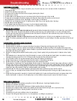
Before changing this alignment, make sure the awl is ad-

justed properly.

• Turn the hand wheel until the needle starts to ascend.

• Locate the cutout, on the bottom rear corner, left side of 

the machine. 

• Insert a screwdriver through the cut out and loosen screw 

Ul-161.

• Apply a wrench to the end of the nut, located to the left of 

the bracket.  

• This nut is part of the rocking shaft (UL-223).  If you turn 

the wrench away from you, the needle will move forward.  

If you move the wrench towards you, the needle will move 

back.

• After setting, tighten screw UL-161.

A

LIgNMeNT


OF


The

 N

eedLe


ANd

 A

wL

UL-161
UL-223

UL-161

Awl - F

RONT


TO

 B

ACk

Both the needle and awl should be approximately 1/16” from 

the front edge of the hole in the needle plate. 

• 

The awl bar can be aligned by adjusting the gibs (UL-

77/78) with the slotted screws on the front face of the 

head. 

• 

There should be no play awl bar, but do not over tighten 

the gibs which will cause the action to bind

Needle - F

RONT


TO

 B

ACk

• 

If there is play in the needle bar adjust the gibs (UL-

197r/l). Do not over tighten the gibs.

• 

Adjust the position of the shuttle housing (UL-235), by 

loosening the four nuts (Ul-229) and move the housing 

forward or back by turning the screws Ul-237. 

• 

once the needle and awl is approximately 1/16” from the 

front edge of the hole in the needle plate, secure the nuts  

(Ul-229).

Summary of Contents for UNION Lockstitch

Page 1: ...UNION Needle and Awl Lock Stitch Sewing Machine Serial Number _______________ Manufactured by Randall Leather Machinery Company 401 Irvine Street Yoakum Texas 77995 USA 1 800 327 9420 or 1 361 293 701...

Page 2: ...mence Sewing 7 ADJUSTMENTS SERVICING Common ADJUSTMENTS 8 OILING CLEANING 8 PRESSER FOOT ADJUSTMENT 9 THREAD Lock 10 THREAD TENSION 10 STITCH LENGTH 10 THREAD Guide ADJUSTMENT 11 Looper Cam ADJUSTMENT...

Page 3: ...wise if you are facing the wheel Use caution and give proper attention to the operation of your machine when sewing Keep your hands away from the needle and awl when the power is on and the machine is...

Page 4: ...ghten the belt tension be lowering the motor with the adjustable motor bracket Lock the motor into postion with the bracket nuts once the fire tension is acheived Pedal Linkage Connect and adjust the...

Page 5: ...wax pot up to the the machine casting and lock in place with the clamping nut Presser Foot Spring Place the upper bracket and spring on top of the machin head With the left hand compress the coil spr...

Page 6: ...is sharp and does not spring or glance off the work when entering the work Synthetic Twisted Natural Cord Needle Size 138 3 cord 1 to 1 1 2 207 4 cord 1 1 2 to 2 277 5 cord 2 1 2 to 3 346 6 cord 3 to...

Page 7: ...he threading wire UL 531 through the wax pot extension and pull the thread through 7 Fig 1 Turn the hand wheel to get access to the lock UL 145 Put the threader through the lock UL 145 grab the thread...

Page 8: ...UL 291 over the bobbin and close the bobbin door Make sure that a length of thread is pulled out of the bobbin door between the spring and the door latch Removing the Bobbin Release the cover latch an...

Page 9: ...consistent even stitch NOTE The machine may be in perfect adjustment and still fail to sew satisfactory if the operator is careless in handling the work or does not adjust the machine to accommodate...

Page 10: ...tion of Common Adjustments Allowing that a machine is in good condition from a standpoint of wear and lost motion a quick check up of the essential settings can be made in the following order Check th...

Page 11: ...rm UL 116 on the top left of the machine if the operator is sitting in front is turned with the 2 screws facing to the left of the machine To make the foot lift higher loosen the inside screw UL 117 a...

Page 12: ...n obtained when the thread pulls out easily with light tension without excessive binding It is recommended to use less tension when working with threads made of natural fibers To give more tension on...

Page 13: ...elay the thread by loosing the screw in the take up cam and moving the screw to the top The looper should hold the thread until it has descended into the material If not the thread would fall off the...

Page 14: ...wl are not bent When the needle and awl are perfectly aligned the needle should comes up through the material without flexing or hitting the sides of the awl hole To see the alignment set a piece of p...

Page 15: ...hat the set screws are both over the flat spots on the shaft which may require the removal of the set screws to locate which are 90 to each other Tighten one set screw then recheck the timing If this...

Page 16: ...the needle when the needle is on the way down and level with the hook point At this position the hook is about to enter the loop When the Take Up UL 135 is at its highest position the point of the ne...

Page 17: ...pointing straight down the thread looper UL 180 is just about to pick the thread Move the hand wheel until the take up is about to desend In this position the Thread Guide UL 165 takes the thread into...

Page 18: ...tretch or excessive coiling especially near the end of a spool 4 Needle not casting off thread after shuttle picks up loop Check needle timing and its position in relation to the shuttle point 5 After...

Page 19: ...ng lever is worn broken or adjusted improperly 2 Check the Presser Foot Bar Spring or weakness or break age 3 Check the lift of the presser foot bar There should be a 1 8 lift at time of feeding work...

Reviews: