background image

OM-51000 & 53000 SERIES       15

Troubleshooting

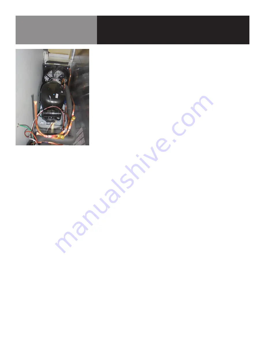
SERVICING THE COMPRESSOR

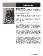
The compressor is part of the sealed refrigeration system and should be replaced by 

a professional service technician.  You can, however, test the compressor and certain 

components.  Prior to testing, unplug the unit and remove the access cover to the 

mechanical housing.  A small box mounted on the side of the compressor protects the 

relay, overload protector, and capacitor.  Release the wire retaining clip that holds the 

cover in place and slip off the cover and the clip.

To test the compressor relay, pull the relay straight off the compressor without twisting 

or damaging it.  If the relay has an external wire coil, hold the relay so that the word 

TOP is up.  Using a multimeter set at RX1, place the probes on terminals S and M.  The 

multimeter needle should not move.  Remove the probe from terminal M and place it on 

the side terminal marked L.  The multimeter needle should not move.  Remove the probe 

from terminal S and place it on terminal M.  The multimeter needle should sweep across 

the scale, indicating full continuity.  

Turn the relay upside down.  Using a multimeter set at RX1, place the probes on terminals 

S and M.  The multimeter needle should sweep across the scale, indicating full continuity.  

Remove the probe from terminal M and place it on the side terminal marked L.  The 

multimeter needle should sweep across the scale, indicating fully continuity.  Remove the 

probe from terminal S and place it on terminal M.  The multimeter needle should not move.   

If the relay fails any of the tests listed above, the relay is faulty and needs to be replaced.  

Push a new relay onto the compressor terminals and replace the terminal cover.  If the 

relay passes all the tests listed above, proceed to testing of the overload protector.  

To remove the overload protector, use a screwdriver to gently pry open the circular spring 

clip that secures the overload protector to the compressor and snap out the overload 

protector.  Pull the two wire connectors off the terminals.  Using a multimeter set at RX1, 

touch a probe to each overload protector terminal.  The multimeter needle should sweep 

across the scale, indicating full continuity.  If the overload protector passes this test, 

proceed to testing of the compressor.  If the overload protector fails this test, the overload 

protector is faulty and needs to be replaced.  Reattach the push-on connectors to the new 

overload protector, clip it in place on the compressor, and replace the terminal cover.

For testing the compressor, use a multimeter set at RX1 to test each of the three terminal 

pins against each of the other two terminal pins.  Each pair should show continuity.  Then, 

with the multimeter set at RX1000, place one probe against the metal housing of the 

compressor (if necessary, scrape off a small amount of paint to ensure contact with 

bare metal).  Place the other probe on each of the three terminals in turn.  If any of the 

three terminals shows continuity with the housing, the compressor is grounded.  If the 

compressor fails either test, call for service at 888-944-7636.  If the compressor passes 

the tests, reinstall the overload protector, relay, terminal cover, and mechanical housing 

cover. 

Summary of Contents for 51000 Series

Page 1: ...UCTIONS AND WARNINGS CONTAINED IN THIS MANUAL WARNING FOR YOUR SAFETY Do not store or use gasoline or other flammable vapors and liquids in the vicinity of this or any other appliance WARNING Improper installation adjustment alteration service or maintenance can cause property damage injury or death Read the installation operating and maintenance instructions thoroughly before installing or servic...

Page 2: ...iven proper maintenance will provide years of trouble free service to its owner In addition all Unified Brands food service equipment is backed by some of the best warranties in the food service industry and by our professional staff of service technicians Retain this manual for future reference NOTICE DUE TO A CONTINUOUS PROGRAM OF PRODUCT IMPROVEMENT UNIFIED BRANDS RESERVES THE RIGHT TO MAKE CHA...

Page 3: ...ces page 2 Warranty Policies page 4 6 Equipment Description page 7 Installation page 8 9 Operation page 10 Maintenance page 11 12 Troubleshooting page 13 15 Parts List page 16 20 Electrical Schematic page 21 23 Service Log page 24 Table of Contents ...

Page 4: ...ity of the customer LABOR COVERAGE In the unlikely event a Unified Brands manufactured unit fails due to defects in materials or workmanship within the first ninety days Unified Brands agrees to pay the contracted labor rate performed by an Authorized Service Agent ASA Any work performed by a non ASA will not be honored by Unified Brands Please consult Unified Brands Technical Support 888 994 7636...

Page 5: ...ndenser cleaning temperature adjustments clogged drains unit leveling and re application of silicone 2 Unified Brands does not cover gaskets under warranty Gaskets are a maintenance type component that are subject to daily wear and tear and are the responsibility of the owner of the equipment Because of the unlimited number of customer related circumstances that can cause gasket failure all gasket...

Page 6: ...age to minimize liability a full inspection is necessary upon arrival Appearance of damage will require removing the crate in the presence of the driver A notation must be placed on the freight bill and signed for by the truck driver at the time of delivery Any and all freight damage that occurs to a Unified Brands piece of equipment as a result of carrier handling is not considered under warranty...

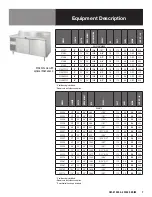
Page 7: ...L LENGTH DEPTH WORK HEIGHT BTU DOORS 2 3 VOLT AMPS NEMA SHIP WT LBS REMOTE 53330 30 33 36 486 1 24 115 5 0 N A 305 53333 33 33 36 523 1 21 1 115 5 0 N A 320 53336 36 33 36 561 1 24 1 115 5 0 N A 335 53339 39 33 36 598 1 27 1 115 5 0 N A 350 53348 48 33 36 895 2 21 115 5 0 N A 380 53351 51 33 36 933 1 21 1 24 115 5 0 N A 395 53354 54 33 36 970 2 24 115 5 0 N A 410 53357 57 33 36 1008 1 24 1 27 115 ...

Page 8: ...asters to ensure they all are in contact with the floor while maintaining a level work surface Adjusting bullet feet heights or shimming casters may be necessary if the floor is not level NOTE Damage to equipment may result if not followed Unified Brands is not responsible for damage to equipment if improperly installed 4 Plug in unit and turn on main on off power switch The main power switch is l...

Page 9: ...Turn bolts clockwise or counterclockwise until the unit is level both right to left and front to back This can be done by hand or with an open end wrench IT IS IMPORTANT THAT A VOLTAGE READING BE MADE AT THE COMPRESSOR MOTOR ELECTRICAL CONNECTIONS WHILE THE UNIT IS IN OPERATION TO VERIFY THE CORRECT VOLTAGE REQUIRED BY THE COMPRESSOR IS BEING SUPPLIED LOW OR HIGH VOLTAGE CAN DETRIMENTALLY AFFECT O...

Page 10: ...o equalize When initially started or when first loaded it can take a long time for temperatures in the display area to stabilize 2 Make sure that unit operation is not being effected by room ambient conditions See Ambient Conditions section above If there are any significant ambient issues adjusting the temperature setting may not help TO RAISE TEMPERATURE 1 Turn knob counterclockwise keeping the ...

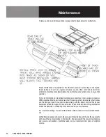
Page 11: ... the cabinet Clean with mild soap and warm water mixture Re install the drawer cartridge by properly aligning the cartridge to the bracket and tightening the round screws 8 Inspect all silicone seams at interior of the base cabinet on a monthly basis Re apply food grade silicone sealant as needed to any seams where silicone has peeled away or cracked Apply silicone to a clean dry surface Allow suf...

Page 12: ... Most repair companies offer this service at very reasonable rates to allow you the time you need to run your business along with the peace of mind that all your equipment will last throughout its expected life These services often offer guarantees as well as the flexibility in scheduling or maintenance for your convenience For a complete listing of current Unified Brands ASAs please visit www uni...

Page 13: ...rty 2 Condenser fan faulty 1 Clean coil 2 Service condenser motor Unit not cold enough 1 Temperature control set too high 2 Temperature control faulty 3 Condenser coil dirty 4 Refrigerant leaking or contaminated 1 Adjust control to lower setting 2 Test control 3 Clean coil 4 Call for service at 888 994 7636 Unit too cold 1 Temperature control set too low 2 Temperature control faulty 1 Adjust contr...

Page 14: ... will feel tension as it grips the bill Repeat this test all around the door If the gasket does not seal tightly replace the gasket after first checking the door for any sagging or warping SERVICING THE CONDENSER FAN Inspectthecondenserfanmotorbyremovingthemechanicalhousingcovertogainaccess Unplug the unit Clean the fan blade and turn it to see if the blade rotates freely If the motor binds replac...

Page 15: ...r needle should not move If the relay fails any of the tests listed above the relay is faulty and needs to be replaced Push a new relay onto the compressor terminals and replace the terminal cover If the relay passes all the tests listed above proceed to testing of the overload protector To remove the overload protector use a screwdriver to gently pry open the circular spring clip that secures the...

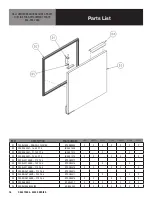
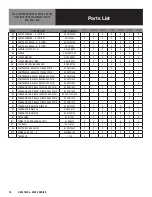
Page 16: ... 5 X 22 5 IN GSK1006 D2 DOOR GASKET 21 75 X 22 5 IN GSK1010 X X D2 DOOR GASKET 24 5 X 22 5 IN GSK1015 X X X X X D3 DOOR LEFT HAND 21 X 24 5 RP DOR0012 D3 DOOR LEFT HAND 24 X 24 5 RP DOR0015 X X D3 DOOR LEFT HAND 27 X 24 5 RP DOR0016 X X X X X D3 DOOR RIGHT HAND 21 X 24 5 RP DOR0013 D3 DOOR RIGHT HAND 24 X 24 5 RP DOR0017 X X X D3 DOOR RIGHT HAND 27 X 24 5 RP DOR0018 X X X X X D4 DOOR HANDLE RP HDL...

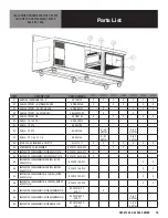
Page 17: ...OM 51000 53000 SERIES 17 Parts List CALL UNIFIED BRANDS SERVICE PARTS HOTLINE FOR REPLACEMENT PARTS 888 994 7636 ...

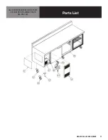
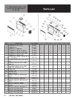
Page 18: ...OR AE4430Y AFTER AUG 2016 RF CMP1406 X X B7 COMPRESSOR AE4430Y BEFORE AUG 2016 RF CMP1406 X X X B7 COMPRESSOR AE4440Y BEFORE AUG 2016 RF CMP1402 X B7 COMPRESSOR AE4450Y BEFORE AUG 2016 RF CMP1403 X B7 CONDENSING UNIT AE4425Y AFTER AUG 2016 RF CON1504 X X X B7 CONDENSING UNIT AE4430Y BEFORE AUG 2016 RF CON1404 X X X X X B7 CONDENSING UNIT AE4430Y AFTER AUG 2016 RF CON1404 HLS X X B7 CONDENSING UNIT...

Page 19: ...DEPTH X 52 DEPTH S4 BULB LED EDISON BASE 3 WATTS EL LGT1411 X X X X X X X S5 EVAPORATOR COIL ASSEMBLY RF CSY0106LR D14 X X S5 EVAPORATOR COILASSEMBLY AFTERAUGUST 2016 RF CSY0106LR D17 X S5 EVAPORATOR COILASSEMBLY BEFOREAUGUST 2016 RF CSY0106LR D14 X S5 EVAPORATOR COILASSEMBLY W CONTROL AFTER AUGUST 2016 RF CSY0106 D17 X X S5 EVAPORATOR COILASSEMBLY W CONTROL BEFORE AUGUST 2016 RF CSY0106 D14 X X S...

Page 20: ...ROUD SINGLE FAN RP SHD1602 X X X X X X X E8 EVAPORATOR FAN MOTOR AXIAL 119MM X 38MM 115V RF FAN1401 X X X E9 EVAPORATOR FAN MOTOR AXIAL 119MM X 38MM 12VDC AFTER AUGUST 2016 RF FAN1402 X X X X E9 SOCKET LIGHT EL LGT360 X X X X X X X E10 GUARD WIRE LIGHT HD GRD1159 X X X X X X X E11 THERMOSTAT CONTROL HD CNT1401 X X X X X X X E12 EVAPORATOR COIL HOUSING END PLATEW LIGHT CUTOUT RP PNL1616 X X E13 EVA...

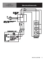
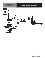
Page 21: ...OM 51000 53000 SERIES 21 Electrical Schematic ALL MODELS EXCLUDING 51386 51395 PASS THRU UNITS ...

Page 22: ...22 OM 51000 53000 SERIES Electrical Schematic MODELS 51386 51395 ...

Page 23: ...OM 51000 53000 SERIES 23 Electrical Schematic ALL PASS THRU MODELS 51347PT 35 52 51368PT 35 52 ...

Page 24: ...24 OM 51000 53000 SERIES Service Log Model No Purchased From Serial No Location Date Purchased Date Installed Purchase Order No For Service Call Date Maintenance Performed Performed By ...

Page 25: ...OM 51000 53000 SERIES 25 ...

Page 26: ......

Page 27: ......

Page 28: ...02 REV C 04 17 1055 Mendell Davis Drive Jackson MS 39272 888 994 7636 601 372 3903 Fax 888 864 7636 unifiedbrands net 2017 Unified Brands All Rights Reserved Unified Brands is a wholly owned subsidiary of Dover Corporation ...

Reviews: