4
OM-SIDE MOUNT WORK TOP REFRIGERATOR
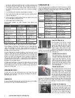
Wiring Diagram
the blade to the motor shaft and pull the blade
off the shaft. Install a new fan blade, replacing
any washers, and tighten the retaining nut. To
test the condenser fan motor, disconnect the
wires to the fan motor. Using a multimeter set
at RX10, touch one probe to each terminal. The
multimeter needle should show approximately
45 to 50 ohms resistance. A lower reading
indicates the motor is faulty and needs to be
replaced.
Next, set the multimeter at RX1000 and touch
one probe to the motor terminals and the other
probe to any unpainted metal part of the unit.
If the multimeter needle moves, the motor is
grounded and needs to be replaced. To remove the motor, unscrew the bracket
that holds the fan motor to its housing. Slide the motor out of the housing. Remove
the fan blade from the old motor and attach to the new motor, replacing any
washers. Install the new motor in its housing by screwing the bracket into place.
Reattach the wires to the motor terminals and reconnect the ground wire.
SERVICING THE COMPRESSOR
The compressor is part of the sealed refrigeration system and should be replaced
by a professional service technician. You can, however, test the compressor and
certain components. Prior to testing, unplug the unit and remove the access cover
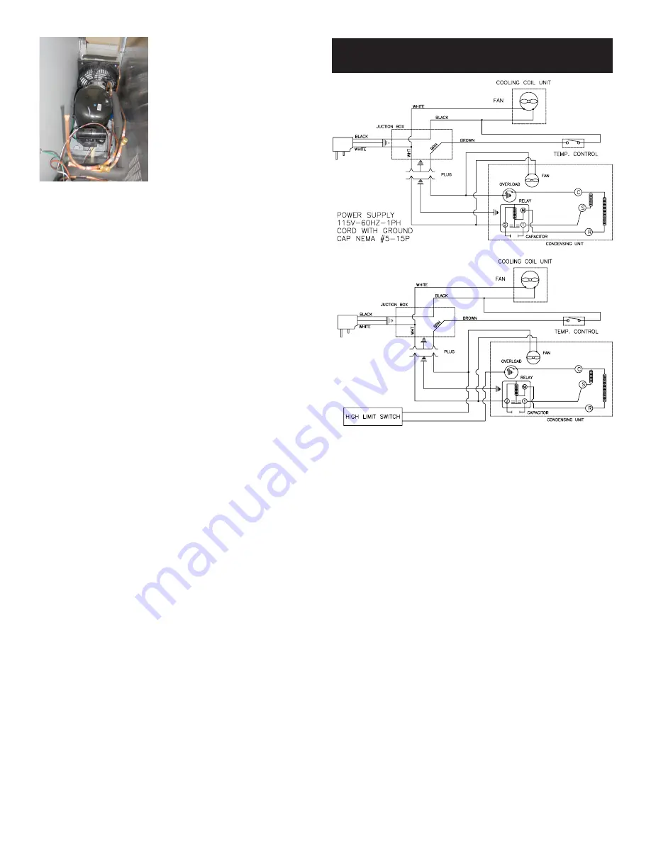
to the mechanical housing. A small box mounted on the side of the compressor
protects the relay, overload protector, and capacitor. Release the wire retaining clip
that holds the cover in place and slip off the cover and the clip.
To test the compressor relay, pull the relay straight off the compressor without
twisting or damaging it. If the relay has an external wire coil, hold the relay so
that the word TOP is up. Using a multimeter set at RX1, place the probes on
terminals S and M. The multimeter needle should not move. Remove the probe
from terminal M and place it on the side terminal marked L. The multimeter needle
should not move. Remove the probe from terminal S and place it on terminal M.
The multimeter needle should sweep across the scale, indicating full continuity.
Turn the relay upside down. Using a multimeter set at RX1, place the probes
on terminals S and M. The multimeter needle should sweep across the scale,
indicating full continuity. Remove the probe from terminal M and place it on the
side terminal marked L. The multimeter needle should sweep across the scale,
indicating fully continuity. Remove the probe from terminal S and place it on
terminal M. The multimeter needle should not move.
If the relay fails any of the tests listed above, the relay is faulty and needs to
be replaced. Push a new relay onto the compressor terminals and replace the
terminal cover. If the relay passes all the tests listed above, proceed to testing of
the overload protector.
To remove the overload protector, use a screwdriver to gently pry open the circular
spring clip that secures the overload protector to the compressor and snap out
the overload protector. Pull the two wire connectors off the terminals. Using a
multimeter set at RX1, touch a probe to each overload protector terminal. The
multimeter needle should sweep across the scale, indicating full continuity. If the
overload protector passes this test, proceed to testing of the compressor. If the
overload protector fails this test, the overload protector is faulty and needs to be
replaced. Reattach the push-on connectors to the new overload protector, clip it in
place on the compressor, and replace the terminal cover.
For testing the compressor, use a multimeter set at RX1 to test each of the three
terminal pins against each of the other two terminal pins. Each pair should show
continuity. Then, with the multimeter set at RX1000, place one probe against the
metal housing of the compressor (if necessary, scrape off a small amount of paint
to ensure contact with bare metal). Place the other probe on each of the three
terminals in turn. If any of the three terminals shows continuity with the housing,
the compressor is grounded. If the compressor fails either test, call for service
at 888-994-7636. If the compressor passes the tests, reinstall the overload
protector, relay, terminal cover, and mechanical housing cover.


