background image


20          

888-994-7636


Trouble Shooting Guide (cont.) 


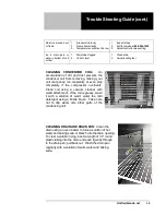
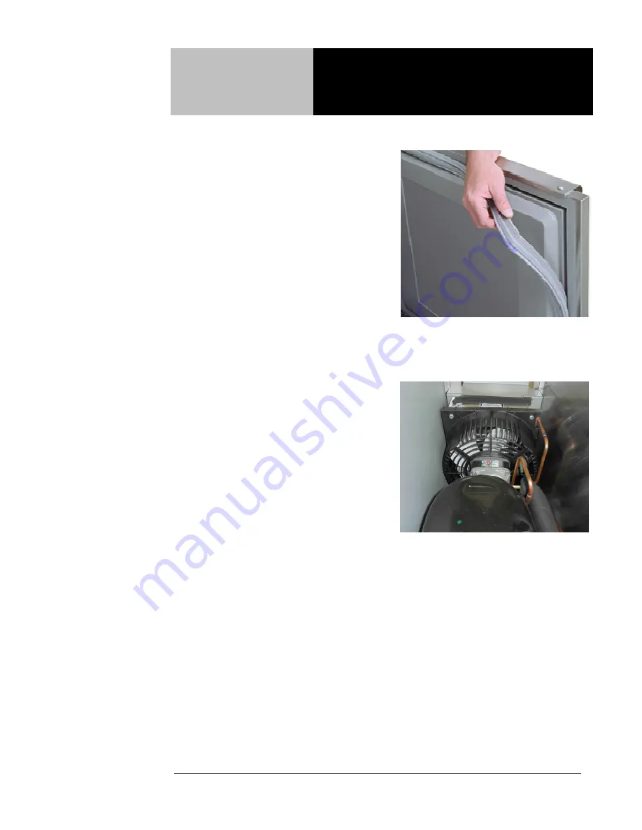
CHECKING THE DOOR SEAL:  Open the 
door and examine all four sides of the door 
gasket for any tears.  Feel the gasket for 
brittleness and/or cracks.  If the gasket 
shows damage, then it must be replaced.  If 
no damage is observed, close the door and 
check the seal between the gasket and the 
cabinet for obvious gaps.  Next open the 
door and close it on a dollar bill.  Slowly pull 
the dollar bill out from the door.  If the 
gasket seals properly, you will feel tension 
as it grips the bill.  Repeat this test all 
around the door.  If the gasket does not seal 
tightly, replace the gasket after first 
checking the door for any sagging or warping.  


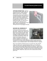
SERVICING THE CONDENSER FAN:  
Inspect the condenser fan motor by 
removing the mechanical housing cover to 
gain access.  Unplug the unit.  Clean the fan 
blade, and turn it to see if the blade rotates 
freely.  If the motor binds, replace it.  If any 
damage to the blade is observed, unscrew 
the retaining nut that holds the blade to the 
motor shaft and pull the blade off the shaft.  
Install a new fan blade, replacing any 
washers, and tighten the retaining nut.  To 
test the condenser fan motor, disconnect 
the wires to the fan motor.  Using a multimeter set at RX10, touch one probe to 
each terminal.  The multimeter needle should show approximately 45 to 50 ohms 
resistance.  A lower reading indicates the motor is faulty and needs to be replaced. 

Next, set the multimeter at RX1000 and touch one probe to the motor terminals 
and the other probe to any unpainted metal part of the unit.  If the multimeter 
needle moves, the motor is grounded and needs to be replaced.  To remove the 
motor, unscrew the bracket that holds the fan motor to its housing.  Slide the motor 
out of the housing.  Remove the fan blade from the old motor and attach to the new 
motor, replacing any washers.  Install the new motor in its housing by screwing the 
bracket into place.  Reattach the wires to the motor terminals and reconnect the 
ground wire. 


Summary of Contents for 9215-32-7

Page 1: ...ds suggests that if you are suspicious of damage to make a notation on the delivery receipt It will be the responsibility of the consignee to file a claim with the carrier We recommend that you do so...

Page 2: ...2 888 994 7636...

Page 3: ...nt purchase of Unified Brands food service equipment and welcome to the growing family of satisfied Unified Brands customers Our reputation for superior products is the result of consistent quality cr...

Page 4: ...ht to make changes in design and specifications without prior notice NOTICE Please read the entire manual carefully before installation If certain recommended procedures are not followed warranty clai...

Page 5: ...event equipment was shipped to a site other than the final installation site Unified Brands will warranty for a period of three months following installation with proof of starting date up to a maximu...

Page 6: ...ondensing unit freight collect in exchange for the return of the defective condensing unit sent back freight prepaid Decisions on whether or not to send complete condensing units will be made by Unifi...

Page 7: ...ormance NOTICE FOOD LOSS IS NOT COVERED UNDER WARRANTY 3 Repairs caused by abuse such as broken glass freight damage or scratches and dents 4 Electrical component failure due to water damage from clea...

Page 8: ...ndeavor whenever practical to meet dealer s request Freight charges to be collect unless otherwise noted DAMAGES All crating conforms to general motor carrier specifications To avoid concealed damage...

Page 9: ...ctory for rate INSTALLATION Equipment installation is the responsibility of the dealer and or their customer Unified Brands requires all equipment to be professionally installed PENALTY CLAUSES Dealer...

Page 10: ...SHELVES CU FT HP VOLT AMPS NEMA SHIP WT 9215 32 7 48 33 36 2 18 11 58 9 5 1 4 115 60 1 6 5 5 15P 325 9205 32 7 60 33 36 2 24 16 21 13 5 1 4 115 60 1 6 5 5 15P 370 9235 32 7 72 33 36 2 27 20 01 20 1 4...

Page 11: ...d dented or rubbing together 2 Check that the condenser and evaporator fans rotate freely without striking any stationary members 3 Unit must be properly leveled check all legs or casters to ensure th...

Page 12: ...ge 3 for location NOTE It is important that a voltage reading be made at the compressor motor electrical connections while the unit is in operation to verify the correct voltage required by the compre...

Page 13: ...eached Before making temperature adjustments A Make sure that you are allowing adequate time for the cabinet temperature to equalize When initially started or when first loaded it can take a long time...

Page 14: ...e mounted to the cabinet with two screws on the upper hinge and a hinge pin on the bottom To adjust the door first open it to 90 and loosen the two screws enough to reposition the door Once reposition...

Page 15: ...asis with a solution of warm water and a mild detergent to extend gasket life 5 Lubricate door hinges with lithium grease NOTE DO NOT USE SHARP UTENSILS AND OR OBJECTS RECOMMENDED CLEANERS FOR YOUR ST...

Page 16: ...er this service at very reasonable rates to allow you the time you need to run your business along with the peace of mind that all your equipment will last throughout its expected life These services...

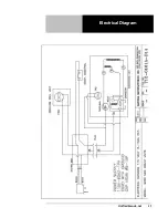
Page 17: ...Unifiedbrands net 17 Electrical Diagram...

Page 18: ...room lower 5 Defrost evaporator 6 Replace door gasket 7 Check door seal Unit not cold enough 1 Temperature control set too high 2 Temperature control faulty 3 Condenser coil dirty 4 Refrigerant leaki...

Page 19: ...your unit cool poorly run constantly or even stop completely if the compressor overheats Clean coil using a vacuum cleaner with wand attachment If the coil is greasy wash it with a solution of warm w...

Page 20: ...or binds replace it If any damage to the blade is observed unscrew the retaining nut that holds the blade to the motor shaft and pull the blade off the shaft Install a new fan blade replacing any wash...

Page 21: ...X1 place the probes on terminals S and M The multimeter needle should sweep across the scale indicating full continuity Remove the probe from terminal M and place it on the side terminal marked L The...

Page 22: ...be against the metal housing of the compressor if necessary scrape off a small amount of paint to ensure contact with bare metal Place the other probe on each of the three terminals in turn If any of...

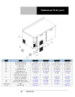
Page 23: ...INGE RIGHT RP HNG9901 RP HNG9901 RP HNG9901 RP HNG9901 D2 GASKET IN GSK1025 IN GSK1020 IN GSK1025 IN GSK1030 GASKET N A N A IN GSK1020 N A D3 REF DOOR ASSEMBLY LEFT RP DOR104 RP DOR102 RP DOR104 RP DO...

Page 24: ...B5 CONDENSER SHROUD T07 1028C D17 T07 1028C D17 T07 1028E D17 T07 1028D D17 B6 CONDENSING UNIT RF CON1406 RF CON1406 RF CON1406 RF CON1406 CONDENSING UNIT CLIPS T07 0500 T07 0500 T07 0500 T07 0500 RE...

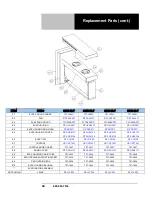
Page 25: ...CLP100 HD CLP100 S2 SHELF SUPPORT BRACKET T07 1501A T07 1501A T07 1501A T07 1501A S3 THERMOMETER HD THR100 HD THR100 HR THR100 HD THR100 S4 WIRE SHELF HD SHL060 HD SHL015 HD SHL060 HD SHL105 WIRE SHEL...

Page 26: ...103 RP SHD0104 RP SHD0103 RP SHD0104 RP SHD0103 RP SHD0104 RP SHD0103 RP SHD0104 E6 EVAP COIL RF COI125 RF COI125 RF COI125 RF COI125 E7 CONTROL HD CNT1401 HD CNT1401 HD CNT1401 HD CNT1401 E7 CONTROL...

Page 27: ...Unifiedbrands net 27 NOTES...

Reviews: