background image


44

44

44

44          


888-994-7636


Replacement 

Parts List 

FX1-4N1 SERIES 

REFRIGERATION SYSTEMS


Summary of Contents for FX-1

Page 1: ...MAGE AT ONCE It is the responsibility of the consignee to inspect the container upon receipt of same and to determine the possibility of any damage including concealed damage Randell suggests that if...

Page 2: ...2 2 2 2 888 994 7636...

Page 3: ...ion page 35 36 Preventive Maintenance page 37 FX 1 2N1 Electrical Diagram page 38 FX1 4N1 Electrical Diagram page 39 Troubleshooting page 40 42 FX 1 2N1 Replacement Parts page 43 47 FX1 4N1 Replacemen...

Page 4: ...ake changes in design and specifications without prior notice NOTICE Please read the entire manual carefully before installation If certain recommended procedures are not followed warranty claims will...

Page 5: ...In the event equipment was shipped to a site other than the final installation site Randell will warranty for a period of three months following installation with proof of starting date up to a maxim...

Page 6: ...k freight prepaid Decisions on whether or not to send complete condensing units will be made by Randell s in house service technician WHEN OPTIONAL LABOR EXTENSION POLICY APPLIES Randell will provide...

Page 7: ...nt failure due to water damage from cleaning procedures QUOTATIONS Verbal quotations are provided for customer convenience only and are considered invalid in the absence of a written quotation Written...

Page 8: ...n MS At dealer s request Randell will endeavor whenever practical to meet dealer s request Freight charges to be collect unless otherwise noted DAMAGES All crating conforms to general motor carrier sp...

Page 9: ...ctory for rate INSTALLATION Equipment installation is the responsibility of the dealer and or their customer Randell requires all equipment to be professionally installed PENALTY CLAUSES Dealer penalt...

Page 10: ...EM 2N1 BASE MODEL 46 29 6 16 4 1 3 0 6 1cc 3 9 1 22kw 1 99kw 115 5 15p 245 FX 1CS FLEXICOLD 1 SECTION 2N1 EQUIPMENT TOP SYSTEM 48 33 24 1 3 0 6 1cc 3 9 1 22kw 1 99kw 115 5 15p 385 FX 2CS FLEXICOLD 2 S...

Page 11: ...33 24 2 6 0 1 8 8cc 1 6 1cc 10 2 2 44 kw 3 98 kw 2 1 kw 1 4 kw 115 5 15p 780 FX2 4N1CSR FLEXICOLD 2 SECTION COMBO EQUIPMENT TOP SYSTEM 2N1 LF 4N1 RT 96 33 24 2 6 0 1 6 1cc 1 8 8cc 10 2 2 44 kw 3 98 kw...

Page 12: ...Check that the condenser and evaporator fans rotate freely without striking any stationary members 3 Unit must be properly leveled check all legs or casters to ensure they all are in contact with the...

Page 13: ...located inside the mechanical housing NOTE It is important that a voltage reading be made at the compressor motor electrical connections while the unit is in operation to verify the correct voltage r...

Page 14: ...14 14 14 14 888 994 7636 Gasket Sealing Adjustment...

Page 15: ...ducts at temperatures 5 F to 40 F Products placed in unit should be pre chilled to the holding temperature This unit is not intended for use as a pull down cabinet 5 The unit is capable of storing any...

Page 16: ...t point temperature B Push and release the up arrow 1 or more times until the desired temperature is displayed Push and release the SET button one time The new set point will flash 3 times and then wi...

Page 17: ...en Defrosts 12 IdF ndF Maximum length of Defrost 30 ndF dSd Start defrost delay 0 dSd dFd Display during Defrost dEF dFd dAd Max display delay after defrost 12 dAd Fdt Drip time after defrost end 3 Fd...

Page 18: ...I SHORT CYCLE DELAY 1 AC AU2 CONDENSER FOR HIGH TEMPERATURE ALARM 230 AU2 rtr P1 P2 PERCENTAGE OF REGULATION 100 rtr AH2 DIFFERENTIAL FOR CONDENSER TEMPERATURE ALARM RECOVERY 4 AH2 CCt CONTINUOUS CYCL...

Page 19: ...randellfx com 19 19 19 19 FX 1 2N1 Control LED Functions USE OF LEDS Each LED function is described in the following table...

Page 20: ...ey for 3 seconds the defrost and water drops symbol will start blinking 2 When a parameter is displayed keep pressed the Set down arrows for more than 7 seconds The Pr2 label will be displayed immedia...

Page 21: ...temperature FIGURE A Your FX1 4N1 Series Unit is equipped with an electronic temperature control Figure A above illustrates the control location on the front above the louvered panel This control is a...

Page 22: ...on Compressor light when lit compressor is running Measurement unit C Celsius F Fahrenheit 1 2 3 4 Refrigerator mode operating set point at 35 F Freezer mode operating set point at 4 F Quick Chill mo...

Page 23: ...used to change the set points in any cycle monitored by the yellow LED upper left corner of button 7 PRINTER used to enable disable the printer if printer is provided monitored by the yellow LED uppe...

Page 24: ...VERT TO STANDARD TEMPERATURE SETTINGS WHEN THE CYCLE IS CHANGED Temperature set points can be changed in cycles H HOLD only TO CHANGE THE TEMPERATURE SETTING FOR CYCLES Follow the instructions HOW TO...

Page 25: ...ellow LED will be displayed Press and hold the SET key until the LED and the yellow LED light on the SET key left top corner is blinking Press the UP key to raise the temperature Press the DOWN key to...

Page 26: ...FERENTIAL FOR SET POINT 4 HY AC ANTI SHORT CYCLE DELAY 1 AC PAU TIME OF STANDBY 0 PAU PFt MAXIMUM ACCEPTANCE DURATION OF POWER FAILURE 15 PFt Con COMPRESSOR ON TIME WITH FAULTY PROBE 15 Con COF COMPRE...

Page 27: ...Oai OSt AUXILIARY OUTPUT TIMER 0 OSt OSS SETPOINT FOR AUXILIARY OUTPUT 0 OSS OSH DIFFERENTIAL FOR AUXILIARY OUTPUT 1 OSH OSi PROBE SELECTION FOR THE SECOND COMPRESSOR RP OSi tdf DEFROST TYPE RE tdf I...

Page 28: ...rS3 ROOM PROBE SET POINT THIRD PHASE 20 rS3 Pd3 MAXIMUM TIME FOR THIRD PROBE OFF Pd3 Pd3 MAXIMUM TIME FOR THIRD PROBE 1 Pd3 dbH DEFROST BEFORE HOLDING PHASE YES dbH dbH DEFROST BEFORE HOLDING PHASE YE...

Page 29: ...29 29 FX1 4N1 Control LED Functions MEANING OF THE LED DISPLAYS A series of light points on the front panels is used to monitor the loads controlled by the instrument Each LED function is described in...

Page 30: ...rackets are designed to fit within the ribs of the insert see Figure 4 2 The FX1 4N1 Rapid Chiller is designed to rapidly cool food product that has been recently cooked down to 40 F To ensure quality...

Page 31: ...first 4 hours of the cycle the system is set to run at full capacity to cool the hot food quickly The next hour is set at a temperature set point to stabilize the product temperature of below 40 F Af...

Page 32: ...cle to use the Product Food Insert Probe press the CYCLE SELECTION key until cycle is selected Press and hold the CYCLE SELECTION key until the display changes to display cyS CYCLE SETTINGS and tin TI...

Page 33: ...l slide easily between the insulated insert and the Evaporator Lid assembly gasket see Figure 9 FIGURE 9 10 HOW TO START THE RAPID CHILL FOOD PRODUCT TEMPERATURE MODE Press and hold the START STOP key...

Page 34: ...E 13 2 The FX1 4N1 Rapid Thawing Mode is designed to rapidly slack defrost frozen food products safely to refrigerated temperatures of 35 40 F The FX1 4N1 safely thaws 20 lbs of frozen product in appr...

Page 35: ...ess the START STOP key The correspondent yellow LED is switched on The Rapid Thaw mode is set and will run for 6 hours During this 6 hour cycle the temperature display on the control may reach above 4...

Page 36: ...ily basis with a solution of warm water and a mild detergent to extend gasket life NOTE DO NOT USE SHARP UTENSILS RECOMMENDED CLEANERS FOR YOUR STAINLESS STEEL INCLUDE THE FOLLOWING JOB CLEANING AGENT...

Page 37: ...CFESA member Most repair companies offer this service at very reasonable rates to allow you the time you need to run your business along with the peace of mind that all your equipment will last throu...

Page 38: ...FAN BLUE L1 BLACK DEFROST YELLOW COMPR BROWN TOP FX 1 2N1 ELECTRICAL DIAGRAM WITH DIXELL XR60CX CONTROL WITH BLUE DISPLAY COMPR BROWN N WHITE FAN BLUE L1 BLACK DEFROST YELLOW L1 BLACK BOTTOM FX 1 2N1...

Page 39: ...OL CONNECTIONS SUPPLY 115V THAW HTR DIXELL XR20C CONTROL CONNECTIONS SUPPLY 115V THAW HTR TOP FX1 4N1 ELECTRICAL DIAGRAM WITH DIXELL XR20C CONTROL SUPPLY 115V NUETRAL HOT N O COM AIR O TRONICS TGKAD16...

Page 40: ...2 Condenser fan faulty 2 Service condenser motor 3 Room ambient too high 3 Reduce room temp to 75F 4 Room humidity too high 4 Set room lower Unit runs constantly 1 Temp control set too high 1 Adjust...

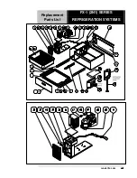
Page 41: ...randellfx com 41 41 41 41 Replacement Parts List FX 1 2N1 SERIES REFRIGERATION SYSTEMS...

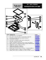
Page 42: ...604 14 CONDENSER FAN AXIAL 127 X 38MM 120 CFM 115V RF FAN0601 15 POWER SUPPLY 115V TO 12VDC 14 4VA MIN EL TRN0601 16 CONDENSER COIL 3 46 x9 00 x5 90 1x 866 3 8 TUBE RF COI0602 17 SOLENOID VALVE 120V C...

Page 43: ...DC EVAPORATOR RF FAN0602 36 DIFFUSER FAN MOUNTING PLATE RP DIF0601 37 GASKET MAGNETIC SLIDE SEAL 29 53 X 23 43 750 X 595mm IN GSK0604 38 HOSE 375 ID X 1 2 OD POLYETHYLENE FLEXIBLE TUBE W ELBOW RP HSE0...

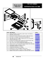
Page 44: ...44 44 44 44 888 994 7636 Replacement Parts List FX1 4N1 SERIES REFRIGERATION SYSTEMS...

Page 45: ...LEFT AND RIGHT SET STAINLESS STEEL HD TRK0602 10 CONDENSATE DRAIN PAN RP CPN0601 11 DRAWER SWITCH COVER RP CVR0702 12 SWITCH BOX RP SWT0601 12A SWITCH BOX AFTER SERIAL T55342 1 RP SWT0701 13 SWITCH DR...

Page 46: ...46 46 46 46 888 994 7636 Replacement Parts List FX1 4N1 SERIES REFRIGERATION SYSTEMS...

Page 47: ...US0701 33 FUSE HOLDER QUICK CONNECT 87F1574 NEWARK SERIES S 8000 EL FUS0301 34 RELAY 16 A 120V COIL ZETTLER AZ9401 1C 120A EL RLY0701 35 CONTROL TIMER 10A 120V AIR O TRONICS TGKAD1600 600AA1H RF CNT07...

Page 48: ...PAN BRACKET FX1 4N1 RP BRK0711 51 EVAPORATOR DRAIN PAN WITH DEFROST HEATER FOR FX1 4N1 RP DRP0701 52 FOIL PAD 6 X 23 DEFROST HEATER 300W 120V EL PAD0701 53 COIL 1 00 X 7 00 X 23 75 STAGED FIN EVAPORAT...

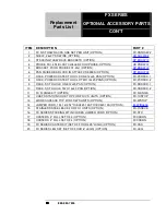
Page 49: ...randellfx com 49 49 49 49 Replacement Parts List FX SERIES OPTIONAL ACCESSORY PARTS...

Page 50: ...OWER COATED TO HOLD TWO 12x20 PANS OPTION FX PCRACK 2 9 RACK SS TO HOLD ONE 12x20 PAN OPTION FX SSRACK 1 10 RACK SS TO HOLD TWO 12x20 PAN OPTION FX SSRACK 2 11 FX FLANGE KIT OPTION FX FLANGE 12 CHEFS...

Page 51: ...randellfx com 51 51 51 51 NOTES...

Reviews: