background image

12

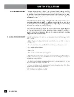
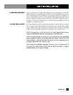
C. ELECTRICAL SUPPLY

D. INSTALLATION CHECKLIST

The wiring should be done by a qualified electrician in accordance with local electrical 

codes. A properly wired, and grounded outlet will assure proper operation. Please consult 

the data plate attached to the compressor to ascertain the correct electrical requirements. 

Supply voltage and amperage requirements are located on the serial number tag located 

inside the far left door.

NOTE: It is important that a voltage reading be made at the compressor motor elec-

trical connections, while the unit is in operation, to verify that the correct voltage 

required by the compressor is being supplied. Low or high voltage can detrimentally 

affect operation and thereby void its warranty.

NOTE: It is important that your unit has its own dedicated line. Condensing units 

are designed to operate with a voltage fluctuation of plus or minus 10% of the volt

-

age indicated on the unit data plate. Burn out of a condensing unit due to exceeding 

voltage limits will void the warranty.

After the final location of the unit has been determined refer to the following checklist 

prior to start up:

1.  Check  all  exposed  refrigeration  lines  to  ensure  that  they  are  not  kinked,  dented  or  

rubbing together.

2. Check that condenser fans rotate freely without striking any stationary members.

3. Unit must be properly leveled.

4. Plug in unit.

5. Turn on cold control located by the compressor.

6. Refer to the front of this manual for serial number location. Please record this informa-

tion in your manual on page 3 now. It will be necessary when ordering replacement parts 

or requesting warranty service.

7. Confirm that unit is holding temperature. Set controls to desired temperature for your 

particular abmient and altitude (See figure B).

8. Allow your unit to operate for approximately 2 hours before putting in food this allows 

interior to cool down to storage temperature.

NOTE: All motors are oiled and sealed.

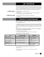
UNIT INSTALLATION

 888-994-7636

Summary of Contents for RAN FRA-1

Page 1: ...suspicious of damage to make a notation on the delivery re ceipt It will be the responsibility of the consignee to file a claim with the carrier We recommend that you do so at once P N OMANUAL_MS 8 10...

Page 2: ...22 Replacement Parts page 23 Section 3 Serving Equipment page 23 Unit Specifications page 24 Unit Parts Congratulations on your recent purchase of Randell food service equipment and welcome to the gr...

Page 3: ...ition all Randell food service equip ment is backed by some of the best war ranties in the food service industry and by our professional staff of service technicians Retain this manual for future refe...

Page 4: ...than final installation Randell will honor the labor warranty for a period of ninety days following installation with proof of starting date up to a maximum of nine months from date of purchase Travel...

Page 5: ...abor or compressors on units shipped outside the United States Any and all freight damage that occurs to a Randell piece of equipment as a result of carrier handling is not considered warranty and is...

Page 6: ...stem EDS you can bank several units together so a common electrical connection point is possible 3 Are the Randell casters non skid type ANSWER Yes 5 Why is my unit leaking all over the floor ANSWER Y...

Page 7: ...S Storage Gallon Model L D H Cu Ft Capacity H P Volts Amps NEMA Ship Wt RAN FRA 1 24 27 35 1 8 6 1 3 115 60 1 6 3 5 15P 200 RAN FRA 2 36 27 35 3 6 12 1 3 115 60 1 6 3 5 15P 230 RANFG FRA 1 26 30 35 5...

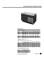
Page 8: ...8 3 4 1 4 115 60 1 5 5 15P 375 RAN SCA 5S 72 30 35 5 64 15 16 x 21 7 8 x 8 3 4 1 4 115 60 1 5 5 15P 425 COMMON DATA FOR SCA SERIES INCLUDES THE STANDARD SCA SERIES AND THE S STORGAE BASE SERIES RANFG...

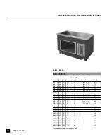
Page 9: ...H P Volts Amps NEMA Ship Wt A Depth Height Frosted Surface RANFG FTA 2 36 30 35 23 x 18 1 4 115V 5 5P 5 250 RANFG FTA 3 48 30 35 35 x 18 1 4 115V 5 5P 5 300 RANFG FTA 4 S 60 30 35 47 x 18 1 4 115V 5 5...

Page 10: ...30 35 3 38 x 20 x 6 175 RAN IC 4S 60 30 35 4 52 x 20 x 6 215 RAN IC 5S 72 30 35 5 67 x 20 x 6 260 RAN IC 6S 86 30 35 6 76 5 x 20 x 6 310 RANFGIC 2 36 30 35 2 250 RANFGIC 3 48 30 35 3 300 RANFGIC 4 60...

Page 11: ...st must be free of vibration and suitably strong enough to support the combined weights of the unit plus the maximum product lad weight which are provided in the table below 2 CLEARANCE There must be...

Page 12: ...10 of the volt age indicated on the unit data plate Burn out of a condensing unit due to exceeding voltage limits will void the warranty After the final location of the unit has been determined refer...

Page 13: ...r flow and heat transfer Failure to maintain this heat transfer will affect unit performance and eventually destroy the compressor Clean the condenser coils with coil cleaner and or a vacuum cleaner a...

Page 14: ...or CEFSA member Most repair companies offer this service at very reasonable rates to al low you the time you need to run your business along with the peace of mind that all your equipment will last t...

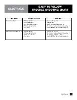
Page 15: ...verload repeatedly tripping 1 Clean coil See 1 2 Service fan and motor See 9 3 Call for service at 888 994 7636 4 Check outlet voltage Unit Runs Constantly 1 Condenser coil dirty 2 Condenser fan fault...

Page 16: ...tor RF ACM005 X X 130 Condensing Unit AEA2410YX RF CON495 X 130A Condensing Unit AEA2413Z RF CON254 X 131 Compressor RF CMP495 X 131A Compressor RF CMP031 X X 134 Start Components RF STR495 X X 134A S...

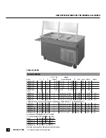
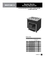
Page 17: ...17 Randell RanServe Hot Food Equipment SECTION 2 UNIT SPECIFICATIONS FOR THE RANDELL HTD SERIES RAN HTD SHOWN randell com...

Page 18: ...eat lamp or display illumination loads must be added to the total amperage COMMON DATA FOR HTD SERIES INCLUDES THE STANDARD HTD SERIES AND THE S STORAGE BASE SERIES Top Work No of 120V Operation 208V...

Page 19: ...rly wired and grounded outlet will assure proper operation Please consult the data plate attached to the compressor to ascertain the correct electrical requirements Supply voltage and amperage require...

Page 20: ...ry 6 months To adjust the flow of air to the burner loosen the Phillips head screw and rotate the shutter to allow more or less air into the burner tube as needed The flames should burn steady with ap...

Page 21: ...ace circuit breaker 4 Test and or replace thermostat see Fig 1 5 Call 888 994 7636 for service agency Individual well will not heat 1 Thermostat off 2 Thermostat defective 3 Defective element 4 Unknow...

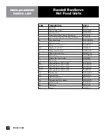
Page 22: ...ket 15 x 27 3 8 IN GSK153 46 Hinge Assembly Door HD HNG300 47 Handle Recessed Door HD HDL1012 49 Lock w Key HD LCK0490 57 Sliding Door Track Guide RP GDE001 116 Thermostat EL HFT230 301 Heating Elemen...

Page 23: ...SW 12 36 27 35 12 120 RAN FGCA 30 30 35 135 RAN FGSW 8 30 30 35 135 RAN FGSW 12 36 30 35 135 RAN FGSW 8PS 36 30 35 135 RAN FGST 2 26 30 35 125 RAN FGST 3 36 30 35 125 RAN FGST 4 48 30 35 125 RAN FGST...

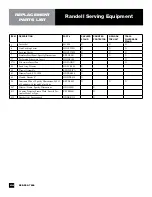
Page 24: ...sions RP PNL001 X X X 27 Perforated Silverware Insert HD INS100 X 27A Silverware Insert Pan HD PAN01V X 49 Lock Assy Drawer HD LCK505 X 60 Drawer Assembly RP DWRICA X 63 Drawer Track S35 1020 HD TRK00...

Reviews: