LM01 I&M MANUAL/EN/11.30.2010
39/65
This document and the information contained herein, is the exclusive property of R&M MATERIALS HANDLING, INC. and represents a non-public, confidential and proprietary trade secret
that may not be reproduced, disclosed to third parties, altered or otherwise emplo
yed in any manner whatsoever without the express written consent of R&M MATERIALS HANDLING, INC.
Copyright © (2010) R&M MATERIALS HANDLING, INC. All rights reserved.
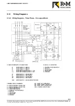
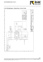
5.12.2 Wiring Diagram – Single Phase – Connections and Components
Connections, Terminals, and Components for Single Phase
L1 – SINGLE PHASE POWER SUPPLY
L2 – SINGLE PHASE NEUTRAL
PE – GROUND
- – MOTOR BRAKE SUPPLY
+ – MOTOR BRAKE SUPPLY
U1V1 – MOTOR SUPPLY
U2 – MOTOR “UP”
V2 – MOTOR “DOWN”
X23 – PUSHBUTTON CONTROL ASSEMBLY PLUG
X22 – OPTIONAL POWER SUPPLY PLUG
NOTE: ROTARY LIMIT SWITCH IS NOT AVAILABLE FOR SINGLE PHASE UNITS.


