R&M Materials Handling, Inc
STAGEMAKER
®
Concert Hoist
Springfield, Ohio USA
Technical Guide
:
800 955-9967
June 2009
www.rmhoist.com
RM-STGMKR-TG-2002-6-ENG.doc
51
®
17 Incremental Encoder
The incremental encoder constantly monitors the position/height of the load and feeds it back to the
controller. With the incremental encoder, the positions are not absolute and need to be reset.
Note:
None of these encoders are short-circuited protected. Therefore, it is very important to check the
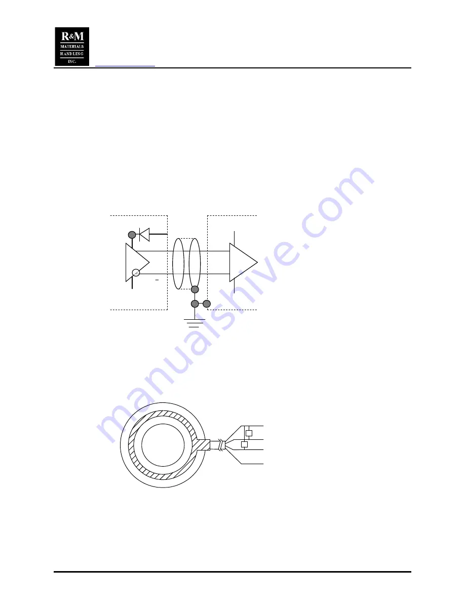
wiring before power is applied. R&M recommends the use of Belden MMICS shielded cable for the motor
cables when an incremental encoder is used.
17.1 SM1 Hoists
The encoder when supplied on the SM1 hoist is mounted next to the brake in the same spot where the
geared limit switch would be mounted. The geared limit switch cannot be furnished if the encoder is
supplied on this hoist. The flange is specially machined and therefore it is not possible to add an encoder
to existing units.
The encoder generates two signals, A and B at 5 pulses per one revolution.
17.2 SM5 or SM10 Hoists
The encoder when supplied on the SM5 or SM10 hoist is a ball bearing with an integrated pulse sensor.
The bearing housing is specially machined and therefore it is not possible to add an encoder to existing
units.
The encoder generates two signals, A and B at 32 or 48 pulses (depends on the hoist size) per one
revolution.
Supply:
3.8<+V<24V
Signal B
Signal A
0V
R
R
1
2
3
4
The required power supply is 24Vdc. Wiring is as follows:
Red wire:
+24Vdc
Black wire:
ground
White wire:
signal A
Blue wire:
signal B
The encoder must be wired through the supplied filter because the encoder is sensitive to induced noise.
The filter does not include the resistors for the 24Vdc.
A
A
OW
11 - 30V
11 – 30V
0V
Wire color identification:
White:
0V
Brown:
+Vcc
Green:
A
Yellow:
B
Gray: Top 0
Pink:
A/
Blue:
B/
Red:0/


