Instrument Tour
R&S
®
Spectrum Rider FPH
66
Getting Started 1321.0996.02 ─ 09
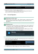
3. Select "Yes" to overwrite existing default alignment data and proceed to per-
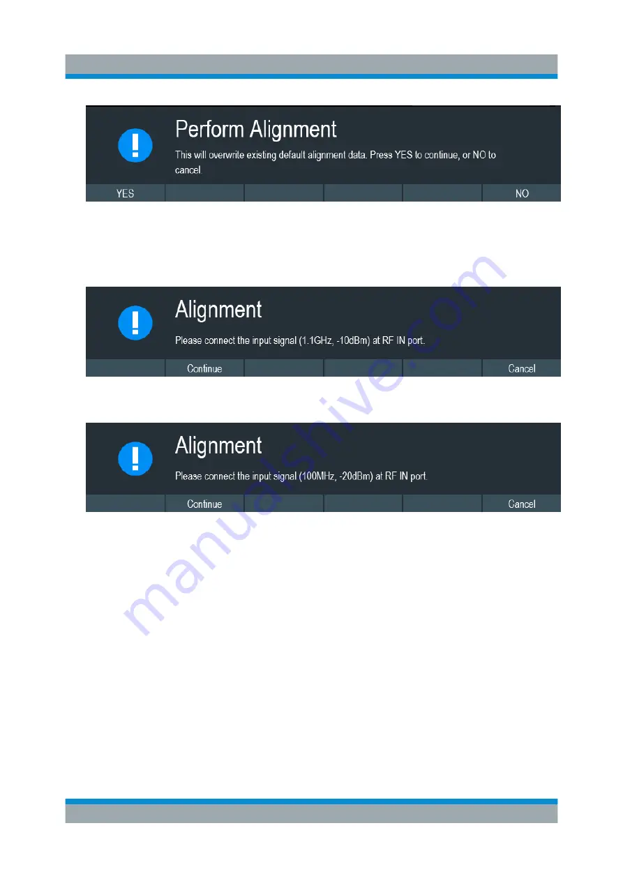
form alignment. The R&S Spectrum Rider displays the "Alignment" dialog.
Depending on the selected alignment item, different input signal is required.
See
and
Figure 4-4: Input signal for frequency clock alignment
Figure 4-5: Input signal for reference level alignment
4. Connect an input signal of 1.1 GHz, -10dBm at the "RF IN" port for frequency
alignment or 100 MHz, -20 dBm at the "RF IN" port for reference level align-
ment.
5. Select "Continue" to start the internal alignment on the instrument.
The R&S Spectrum Rider overwrites existing adjustment data and performs
the internal alignment.
If wrong input signal is detected, the R&S Spectrum Rider displays a message
of a failed alignment dialog.
Configuring the R&S Spectrum Rider

