Trying Out the Instrument
R&S
®
Spectrum Rider FPH
88
Getting Started 1321.0996.02 ─ 09
The ratio between the forward and reverse power is a measure of the load match-
ing. The R&S Spectrum Rider displays it as the return loss or standing wave ratio.
The power sensors for the R&S Spectrum Rider have an asymmetrical design.
Therefore, they have to be inserted into the test setup in such a way that the "For-
ward" arrow on the sensor points toward the load (in the direction of the power
flux).
When measuring high powers, pay strict attention to the following instructions to
avoid personal injury and to prevent the power sensor from being destroyed.
Danger of skin burns and damage to the instrument
●
Never exceed the permissible continuous power.
●
See diagram on the rear of the sensor for the permissible continuous
power.
●
Turn off the RF power to connect the sensor.
●
Screw the RF connectors tightly.
Test setup
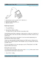
Connect the power sensor cable to the USB port of R&S Spectrum Rider. If the
power sensor is having the binder connector (i.e R&S FSH-Z14, R&S FSH-Z44),
the FSH-Z144 adaptor cable is needed. Insert the directional power sensor
between the source and the load.
The power sensors for the R&S Spectrum Rider have an asymmetrical design.
Hence, you have to insert them into the test setup in such a way that the "For-
ward" arrow (1
➙
2) on the sensor points toward the load (= in the direction of the
power flux).
Using a Power Sensor

