Common Analysis and Display Functions
R&S
®
FSVA3000/ R&S
®
FSV3000
425
User Manual 1178.8520.02 ─ 01
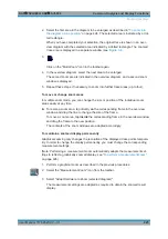
2. Select the first area in the diagram to be enlarged as described in
on page 424. The selected area is indicated by a dot-
ted rectangle.
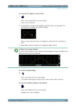
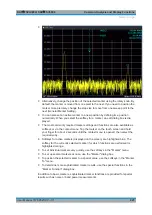
When you have completed your selection, the original trace is shown in an over-
view diagram with the selected area indicated by a dotted rectangle. The zoomed
trace area is displayed in a separate window (see
3.
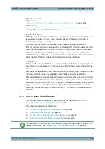
Click on the "Multi-Zoom" icon in the toolbar again.
4. In the overview diagram, select the next area to be enlarged.
The second zoom area is indicated in the overview diagram, and a second zoom
window is displayed.
5. Repeat these steps, if necessary, to zoom into further trace areas (up to four).
To move or change zoom areas
In multiple zoom mode, you can change the size or position of the individual zoom
areas easily at any time.
► To resize a zoom area, tap directly
on
the corresponding frame in the overview
window and drag the line to change the size of the frame.
To move a zoom area, tap
inside
the corresponding frame in the overview window
and drag the frame to the new position.
The contents of the zoom windows are adapted accordingly.
To maintain a zoomed display permanently
Graphical zooming only changes the resolution of the displayed trace points tempora-
rily. In order to change the display permanently, you must change the corresponding
measurement settings.
(Note: Performing a measurement zoom automatically adapts the measurement set-
tings to reflect a graphically zoomed display, see
"To perform a measurement zoom"
1. Perform a graphical zoom as described in the previous procedures.
2. Select the "Measurement Zoom" icon from the toolbar.
3. Select "Adapt Hardware to Zoom (selected diagram)".
The measurement settings are adapted as required to obtain the zoomed result
display.
Zoomed Displays

