Common Analysis and Display Functions
R&S
®
FSVA3000/ R&S
®
FSV3000
503
User Manual 1178.8520.02 ─ 01
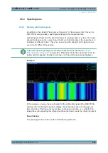
ing to the size of the window. All other spectrogram settings are identical for 3-dimen-
sional and 2-dimensional spectrograms.
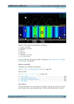
When the measurement is stopped or completed, the currently selected frame is indi-
cated by a gray vertical plane. (As opposed to the small white arrows at the borders of
the 2-dimensional display.) The spectrum diagram always displays the spectrum for the
currently selected frame.
By default, the most recently recorded frame (frame 0) is selected, and added at the
front of the diagram.
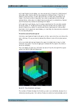
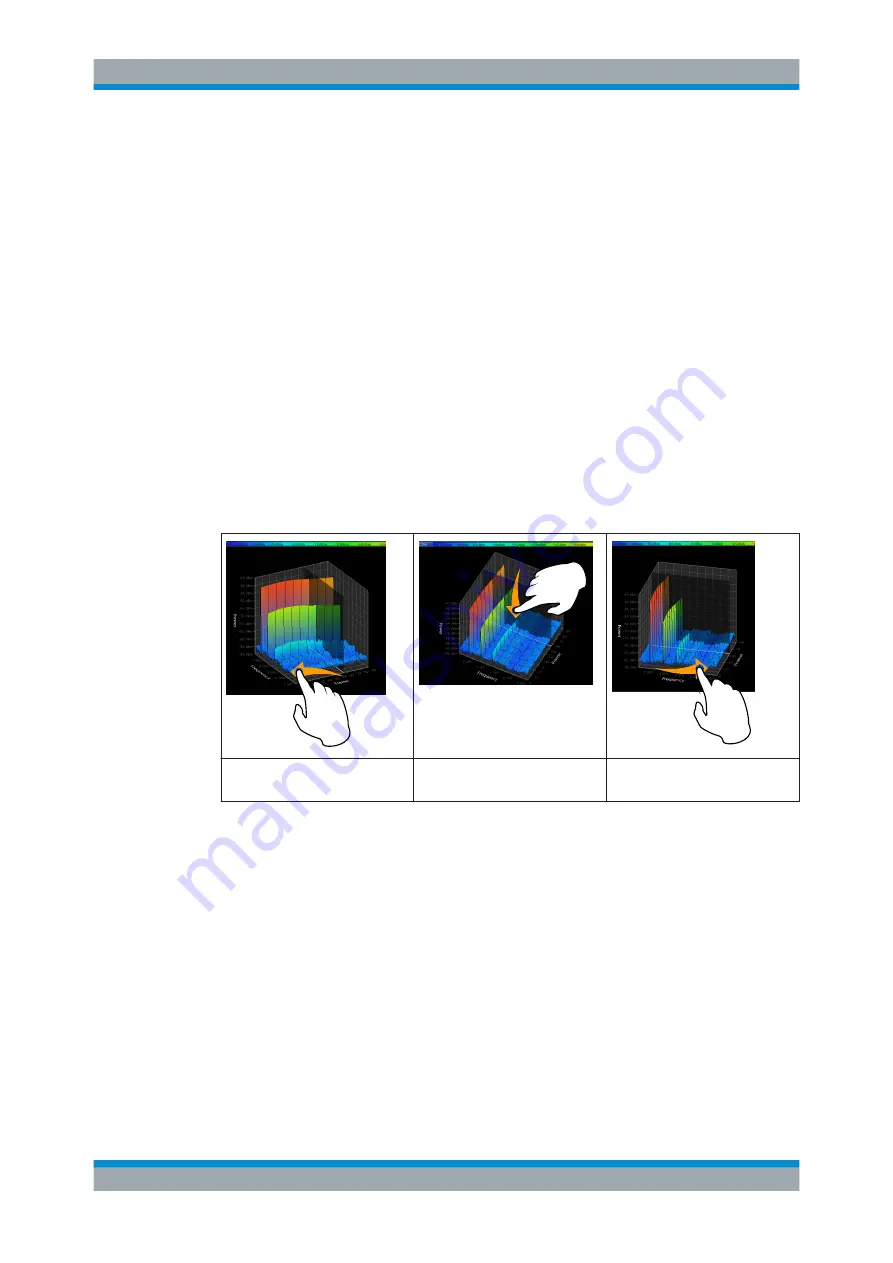
Rotating the spectrogram in three dimensions
Depending on which aspect of the spectrogram is currently of interest, you can rotate
the display to have a closer look at the frequency, the time, or the power dimension.
Simply drag your finger or the mouse pointer over the spectrogram in the direction you
want to rotate it. You can rotate the display left or right, up and down. Note, however,
that the degree of rotation is restricted in the upward direction to avoid confusing
views. If you rotate the spectrogram such that you see the frequency-frame-plane
directly from above, the display is identical to the 2-dimensional spectrogram.
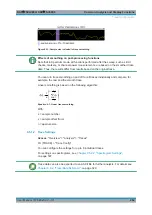
Table 9-6: Effect of rotating the spectrogram in three dimensions
Rotation to the left > focus on
frame
Rotation down > focus on fre-
quency and frame
Rotation to the right > focus on
frequency
Markers in three-dimensional spectrograms
In three-dimensional spectrograms, the markers are indicated by the common arrows
used in the spectrum display, for example. New markers are automatically placed on
the current frame. You can move the markers to any position in all dimensions of the
diagram. When you select a marker on the screen, three-dimensional cross-hairs indi-
cate the position on all axes.
Sometimes, a marker can be hidden by other frames. If necessary, rotate the spectro-
gram or select a different frame as the current frame.
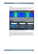
Color Maps
Spectrograms assign power levels to different colors to visualize them. The legend
above the spectrogram display describes the power levels the colors represent.
Trace Configuration


