

Remote Commands
R&S
®
FSVA3000/ R&S
®
FSV3000
1027
User Manual 1178.8520.02 ─ 01
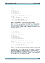
Example:
INIT:CONT OFF
Switches to single sweep mode
CALC:MARK:FUNC:NDBD ON
Switches on the n dB down function.
INIT;*WAI
Starts a sweep and waits for the end.
CALC:MARK:FUNC:NDBD:TIME?
Outputs the time values of the temporary markers.
Usage:
Query only
Manual operation:
See
14.8.3.13
Signal Count Marker
The following commands control the frequency counter.
.............................................................................. 1027
CALCulate<n>:MARKer<m>:COUNt:FREQuency?
..........................................................1028
CALCulate<n>:MARKer<m>:COUNt:RESolution
.............................................................1028
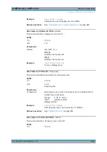
CALCulate<n>:MARKer<m>:COUNt
<State>
This command turns the frequency counter at the marker position on and off.
The frequency counter works for one marker only. If you perform a frequency count
with another marker, the R&S
FSV/A deactivates the frequency count of the first
marker.
To get a valid result, you have to perform a complete measurement with synchroniza-
tion to the end of the measurement before reading out the result. This is only possible
for single sweep mode.
See also
Suffix:
<n>
.
<m>
Parameters:
<State>
ON | OFF | 0 | 1
OFF | 0
Switches the function off
ON | 1
Switches the function on
Analyzing Measurements (Basics)


