Common Measurement Settings
R&S
®
FSVA3000/ R&S
®
FSV3000
325
User Manual 1178.8520.02 ─ 01
8.2.4
Optional External Generator Control
If the R&S
FSV/A optional External Generator Control is installed, you can operate var-
ious commercially available generators as an external generator with the R&S
FSV/A.
Thus, scalar network analysis with the R&S
FSV/A is possible.
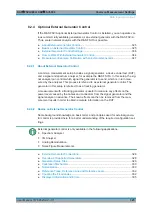
About External Generator Control
.........................................................................325
Basics on External Generator Control
...................................................................325
External Generator Control Settings
..................................................................... 336
How to Work With External Generator Control
..................................................... 344
Measurement Example: Calibration with an External Generator
.......................... 347
8.2.4.1
About External Generator Control
A common measurement setup includes a signal generator, a device under test (DUT),
and a signal and spectrum analyzer, for example the R&S
FSV/A. In this setup, the sig-
nal analyzer can control which signal the generator is to send, which is in turn mea-
sured by the analyzer. This process is referred to as
external generator control
. The
generator in this setup is referred to as a
tracking generator
.
A measurement with a tracking generator is useful to measure any effects on the
power level caused by the cables and connectors from the signal generator and the
signal analyzer in advance. The known effects can then be removed from the mea-
surement results in order to obtain accurate information on the DUT.
8.2.4.2
Basics on External Generator Control
Some background knowledge on basic terms and principles used for external genera-
tor control is provided here for a better understanding of the required configuration set-
tings.
External generator control is only available in the following applications.
●
Spectrum Analyzer
●
I/Q Analyzer
●
Analog Demodulation
●
Noise Figure Measurements
External Generator Connections
...........................................................................326
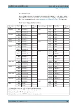
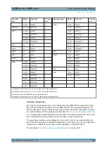
Overview of Supported Generators
.......................................................................328
...........................................................................................329
..........................................................................................330
Reference Trace, Reference Line and Reference Level
.......................................332
..................................................................................... 332
Displayed Information and Errors
..........................................................................335
Data Input and Output

