Common Measurement Settings
R&S
®
FSVA3000/ R&S
®
FSV3000
358
User Manual 1178.8520.02 ─ 01
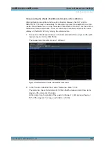
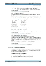
3. Set the trigger to be used to "Output".
(Note: Trigger 2 is output to the front panel connector, Trigger 3 is output to the rear
panel connector. For R&S
FSV/A85 models with two RF input connectors, Trigger
2 is not available.)
4. Define whether the trigger signal is to be output automatically ("Output Type" =
"Device triggered" or "Trigger Armed") or whether you want to start output manually
("Output Type" = "User-defined").
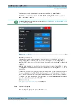
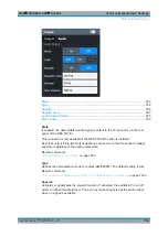
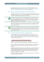
5. For manual output: Specify the constant signal level and the length of the trigger
pulse to be output. Note that the level of the trigger pulse is opposite to the con-
stant output "Level" setting (compare the graphic on the "Send Trigger" button).
6. Connect a device that will receive the trigger signal to the configured Trigger 2
Input / Output connector.
7. Start a measurement and wait for an internal trigger, or select the "Send Trigger"
button.
The configured trigger is output to the connector.
8.3
Frequency and Span Configuration
The frequency and span settings define the scope of the signal and spectrum to be
analyzed with the R&S
FSV/A.
Impact of the Frequency and Span Settings
.........................................................358
...............................................................................360
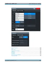
Keeping the Center Frequency Stable - Signal Tracking
...................................... 364
How To Define the Frequency Range
................................................................... 365
How to Move the Center Frequency through the Frequency Range
8.3.1
Impact of the Frequency and Span Settings
Some background knowledge on the impact of the described settings is provided here
for a better understanding of the required configuration.
Defining the Scope of the Measurement - Frequency Range
...............................358
Stepping Through the Frequency Range - Center Frequency Stepsize
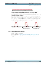
Coping with Large Frequency Ranges - Logarithmic Scaling
............................... 359
8.3.1.1
Defining the Scope of the Measurement - Frequency Range
The frequency range defines the scope of the signal and spectrum to be analyzed. It
can either be defined as a span around a center frequency, or as a range from a start
to a stop frequency. Furthermore, the full span comprising the entire possible fre-
quency range can be selected, or a zero span. The full span option allows you to per-
form an overview measurement over the entire span. Using the "Last Span" function
you can easily switch back to the detailed measurement of a specific frequency range.
Frequency and Span Configuration

