Getting Started
R&S
®
FSVA3000/ R&S
®
FSV3000
54
User Manual 1178.8520.02 ─ 01
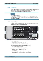
16 = REF In/Out connectors
17 = Trigger 2 (In/Out) connector
18 = Noise Source Control (requires option R&S
FSV3-B28V)
5.2.2.1
AC Power Supply Connection and Main Power Switch
An AC power supply connector and main power switch are located in a unit on the rear
panel of the instrument.
Main power switch function:
Position 1: The instrument can be started via the Power key on the front panel. The
(optional) OCXO reference frequency is warmed up.
Position O: The entire instrument is disconnected from the AC power supply.
Chapter 5.1.1.4, "Connecting the AC Power"
5.2.2.2
Display Port and DVI
You can connect an external monitor or other display device to the R&S
FSV/A to pro-
vide an enlarged display. Two different types of connectors are provided for this pur-
pose:
●
Display Port
●
DVI (digital visual interface)
The Display Port requires option R&S
FSV3-B114.
For details, see
Chapter 5.1.4, "Connecting an External Monitor"
5.2.2.3
LAN
The LAN interface can be used to connect the R&S
FSV/A to a local network for
remote control, printouts or data transfer. The assignment of the RJ-45 connector sup-
ports twisted-pair category 5 UTP/STP cables in a star configuration (UTP stands for
unshielded twisted pair
, and STP for
shielded twisted pair
).
A second LAN 10GBase-T connector is provided for remote control or fast I/Q data
transfer.
For details, see
Chapter 13, "Network and Remote Operation"
5.2.2.4
USB
The rear panel provides four additional female USB (USB-A) connectors to connect
devices like a keyboard, a mouse or a memory stick (see also
Furthermore, a male USB Device connector (USB-B) is provided optionally, for exam-
ple to connect the R&S
FSV/A to a PC for remote control. The device connector
requires R&S
FSV3-B114.
Instrument Tour

