Configuration
R&S
®
FSW-K7
117
User Manual 1173.9240.02 ─ 23
........................................................................................... 119
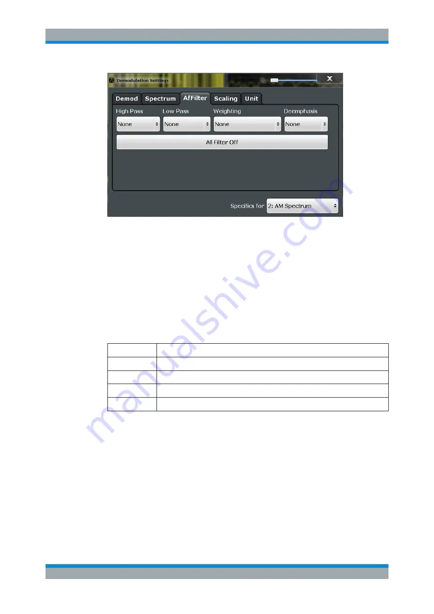
High Pass
Defines a high pass filter with the given limit to separate the DC component. The filters
are indicated by the 3 dB cutoff frequency. The 50 Hz and 300 Hz filters are designed
as 2nd-order Butterworth filter (12 dB/octave). The 20 Hz filter is designed as 3rd-order
Butterworth filter (18 dB/octave).
The high pass filters are active in the following demodulation bandwidth range:
None
No AF Filter used (default)
20 Hz
100 Hz ≤ demodulation bandwidth ≤ 1.6 MHz
50 Hz:
200 Hz ≤ demodulation bandwidth ≤ 3 MHz
300 Hz:
800 Hz ≤ demodulation bandwidth ≤ 8 MHz
Manual:
A high pass filter with the manually defined frequency is used.
Note:
If online demodulation output is active, the predefined (fixed) filters are not avail-
able. In this case, the frequency for the high pass filter must be defined manually (see
also
Chapter 5.8.2, "Analog Demodulation Output Settings"
If a filter was already configured when online demodulation output is activated, it is
replaced by a manual filter that provides corresponding results, if possible.
Remote command:
[SENSe:]FILTer<n>:HPASs[:STATe]
[SENSe:]FILTer<n>:HPASs:FREQuency[:ABSolute]
[SENSe:]FILTer<n>:HPASs:FREQuency:MANual
Low Pass
Defines a low pass filter type. Relative and absolute low pass filter are available.
Demodulation


