Instrument Functions
R&S
®
NGE100B
27
User Manual 5601.1343.02 ─ 02
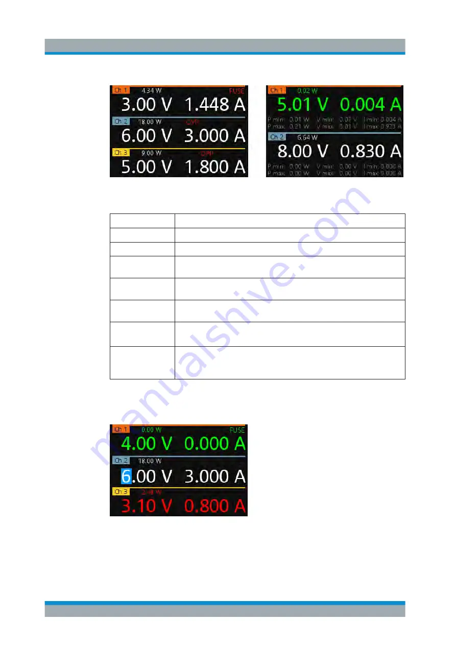
Figure 5-2: Channel display area for 3-channel and 2-channel instrument
Table 5-3: Available parameters in the channel display area
Parameter
Description
Channel
Display channel number.
Power
Display output power in Watt.
Voltage
Voltage in Volt. The display resolution for voltage is two digits after the decimal
point.
Current
Current limit in Ampere. The display resolution for current is three digits after the
decimal point.
Fuse
Indicator to show the fuse status (on or off). When triggered, the indicator shows
flashing and displays in red.
OVP/OPP/OTP
Indicator to show that the overload voltage or current protection is triggered.
When triggered, the indicator shows flashing and displays in red.
Channel history infor-
mation
Only available in a 2-channel instrument.
It records and displays the historical maximum and minimum channel information
(P min, P max, V min, V max, I min, I max).
Different font colors on the screen are used to differentiate the various output status
and operating condition of the instrument. It is easy to know and confirm the different
output status and operating conditions of the instrument by looking at the colors.
Figure 5-3: Color coding of operating condition
User Interface
www.allice.de
Allice Messtechnik GmbH


